


Programming 180
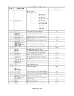
Motor Overload
L1-01
Motor Overload Protection
Selection
MOL Fault Select
Sets the motor thermal overload protection (OL1) based on the
cooling capacity of the motor.
0: Disabled
1: Standard Fan Cooled (< 10:1 motor)
2: Standard Blower Cooled (
≥
10:1 motor)
3: Vector Motor (
≤
1000:1 motor)
0 to 3
1
Q
Q
Q
Q
L1-02
Motor Overload Protection
Time
MOL Time Const
Sets the motor thermal overload protection (OL1) time. A larger
L1-02 time will increase the time before an OL1 fault will occur.
0.1 to
20.0
8.0min
A
A
A
A
L1-03
Motor Overheat Alarm
Operation Selection
Mtr OH Alarm Sel
Sets operation selection when the motor temperature analog input
(H3-09 = E) exceeds the OH3 alarm level (1.17V)
0: Ramp to Stop
1: Coast to Stop
2: Fast-Stop
3: Alarm Only
0 to 3
3
A
A
A
A
L1-04
Motor Overheat Fault
Operation Selection
Mtr OH Fault Sel
Sets stopping method when the motor temperature analog input
(H3-09 = E) exceeds the OH4 fault level (2.34V).
0: Ramp to Stop
1: Coast to Stop
2: Fast-Stop
0 to 2
1
A
A
A
A
L1-05
Motor Temperature Input
Filter Time
Mtr Temp Filter
This parameter adjusts the filter on the motor temperature analog
input (H3-09 = E). Increase to add stability, decrease to improve
response.
0.00 to
10.00
0.20sec
A
A
A
A
Power Loss Ridethru
L2-01
Momentary Power Loss
Detection Selection
PwrL Selection
Enables and disables the momentary power loss function.
0: Disabled - Drive trips on (UV1) fault when power is lost.
1: Power Loss Ride Thru Time - Drive will restart if power returns
within the time set in L2-02.*
2: CPU Power Active - Drive will restart if power returns prior to
control power supply shut down.*
* In order for a restart to occur, the run command must be
maintained throughout the ride thru period.
0 to 2
0
A
A
A
A
L2-02
Momentary Power Loss
Ride-thru Time
PwrL Ridethru t
Sets the power loss ride-thru time. This value is dependent on the
capacity of the Drive. Only effective when L2-01 = 1.
0.0 to
25.5sec
Varies
by
kVA
A
A
A
A
L2-03
Momentary Power Loss
Minimum Base Block Time
PwrL Baseblock t
Sets the minimum time to wait to allow the residual motor voltage
to decay before the Drive output turns back on during power loss
ride thru. After a power loss, if L2-03 is greater than L2-02,
operation resumes after the time set in L2-03.
0.1 to
5.0sec
Varies
by
kVA
A
A
A
A
L2-04
Momentary Power Loss
Voltage Recovery Ramp
Time
PwrL V/F Ramp t
Sets the time it takes the output voltage to return to the preset V/F
pattern after speed search (current detection mode) is complete.
0.0 to
5.0sec
Varies
by
kVA
A
A
A
A
L2-05
Undervoltage Detection
Level
PUV Det Level
Sets the Drive's DC Bus undervoltage trip level. If this is set lower
than the factory setting, additional AC input reactance or DC bus
reactance may be necessary. Consult the factory before changing
this parameter setting.
150 to
210
190
Vdc
A
A
A
A
L2-06
KEB Deceleration Rate
KEB Decel Time
Sets the time required to decelerate to zero speed when a KEB
command is input from a multi-function input.
0.0 to
200.0
0.0sec
A
A
A
A
L2-07
Momentary Recovery Time
UV Return Time
Set the time (in seconds) to accelerate to the set speed after
recovery from a momentary power loss. If setting = 0.0, then active
acceleration time is used instead.
0.0 to
25.5
0.0sec
A
A
A
A
L2-08
Frequency Reduction Gain at
KEB Start
KEB Frequency
Sets the percentage of output frequency reduction at the beginning
of deceleration when a KEB command is input from multi-function
input.
Reduction = slip frequency before KEB operation
×
L2-08
×
2
0 to 300
100%
A
A
A
A
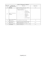
Denotes that parameter can be changed when the Drive is running.
Table A.1 F7 Parameter List (Continued)
Parameter
No.
Parameter Name
Digital Operator Display
Description
Setting
Range
Factory
Setting
Control Method
V/F
V/F
w/
PG
Open
Loop
Vector
Flux
Vector
Содержание Varispeed f7
Страница 1: ...F7 Drive Programming Manual Model CIMR F7U Document Number TM F7 02...
Страница 2: ......
Страница 8: ...vi Notes...
Страница 158: ...Programming 150 Notes...