Fuel tank and fuel pump module
4-14
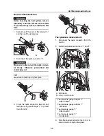
3.
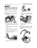
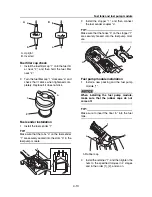
Apply a thin coat of engine oil to the con-
tact surfaces of the fuel pipe “a”.
4.
Connect the quick connector “1” onto the
fuel pipe “a”.
5.
Push down on the retainer “b” until it clicks.
6.
Connect the fuel sender coupler “c” and
fuel pump module coupler “d”.
TIP:
• If the quick connector “1” is not installed com-
pletely onto the fuel pipe “a”, the retainer “b”
cannot be pushed down.
• Check that the quick connector “1” is correct-
ly installed by making sure there is a small
amount of free play when the quick connec-
tor is pulled and pushed. If there is no free
play in the quick connector “1”, disconnect
the fuel hose and check the O-rings for dam-
age and proper installation.
7.
Install the service lid. See “Front hood”
(8-6).
Fuel tank installation
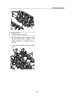
1.
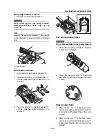
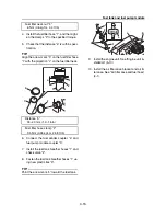
Install the fuel tank “1”, and then fasten the
fuel tank using the straps “2”.
TIP:
• Install the straps “2” so that the rubber band
portions “a” of the straps are positioned on
top.
• Make sure that the metal loops “b” on the end
of the straps “2” are hooked securely onto the
holders on the hull.
2.
Install a new packing “1”, fuel filler neck
“2”, and the fuel filler cap “3”.
3.
Tighten the nut “4” to the specified torque.
TIP:
Align the projection “a” on the fuel filler neck “2”
with the holes “b” in the packing “3” and deck.
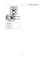
Fuel pump module nut
1st: 3.5 Nm (0.35 kgf·m, 2.58 ft·lb)
2nd: 7 Nm (0.7 kgf·m, 5.2 ft·lb)
1
[4]
[8]
[7]
[2]
[3]
[5]
[9]
[6]
[1]
b
d
c
a
1
1
2
2
b
b
b
b
a
a
3
2
1
b
4
a
Содержание Waverunner VXS VX1800
Страница 1: ...SERVICE MANUAL WaveRunner VXS VX1800 F2W VXR VX1800A F2W F2W 28197 ZU 11 ...
Страница 12: ...How to use this manual 1 7 UP Upside YDIS Yamaha Diagnostic System Abbreviation Description ...
Страница 32: ...Technical tips 1 27 Trolling Neutral Neutral Reverse Engine stopped Condition Lever Reverse gate ...
Страница 40: ...Technical tips 1 35 MEMO ...
Страница 163: ...Oil separator tank and oil pan 5 72 3 4 4 4 4 4 9 4 1 5 6 10 11 7 2 3 8 ...
Страница 179: ...Crankcase connecting rod and piston 5 88 Crankcase bolt 1 10 Nm 1 0 kgf m 7 4 ft lb 12 11 10 4 2 6 8 9 3 1 5 7 1 ...
Страница 180: ...Crankcase connecting rod and piston 5 89 MEMO ...
Страница 196: ...6 15 Impeller drive shaft and impeller duct Impeller duct bolt 5 40 Nm 4 0 kgf m 29 5 ft lb 1 3 2 5 5 5 5 4 3 ...
Страница 204: ...6 23 Intermediate housing Intermediate housing bolt 2 17 Nm 1 7 kgf m 12 5 ft lb 1 2 3 ...
Страница 205: ...Intermediate housing 6 24 MEMO ...
Страница 251: ...Indication system 7 44 MEMO ...
Страница 253: ...8 Hull and hood Rear section 8 31 Spout installation 8 33 Reboarding step installation VXR 8 33 Deck and hull 8 34 ...
Страница 278: ...8 25 Exhaust system 6 Install the band Rubber hose clamp 2 3 5 Nm 0 35 kgf m 2 58 ft lb ...
Страница 290: ...Deck and hull 8 37 MEMO ...
Страница 312: ...Engine unit troubleshooting 9 21 MEMO ...
Страница 313: ...A Appendix Wiring diagram A 1 How to use the wiring diagram A 1 VXS VXR A 2 ...
Страница 317: ......
Страница 318: ...Mar 2015 CR E ...

