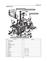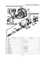
Jet pump unit
6-4
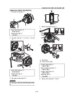
3.
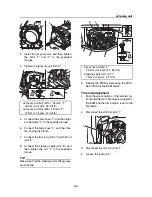
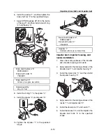
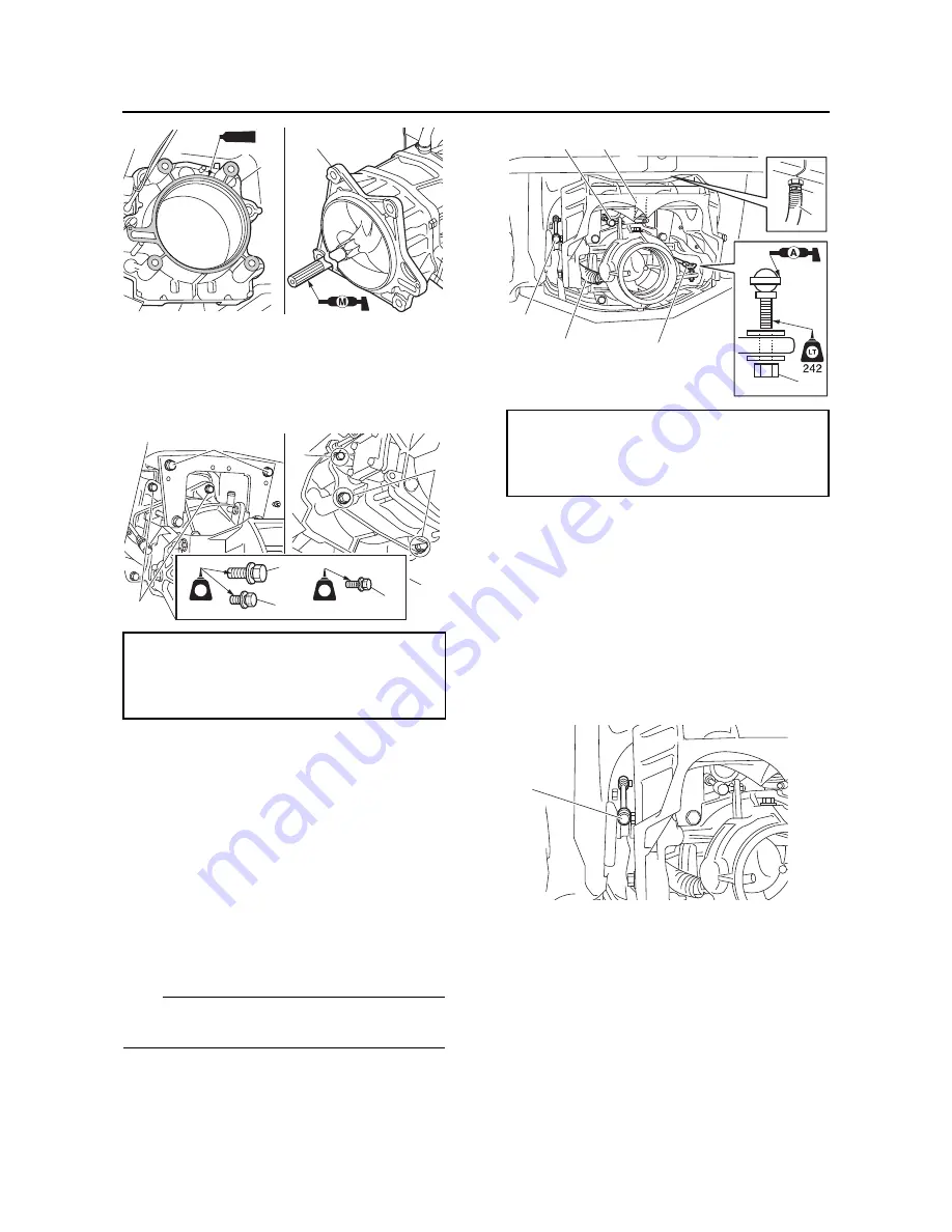
Install the jet pump unit, and then tighten
the bolts “1” and “2” to the specified
torques.
4.
Tighten the jet pump unit bolt “3”.
5.
Connect the spout hose “1”, and then tight-
en the clamp “2” to the specified torque.
6.
Connect the bilge hose “3”, and then fas-
ten it using the clamp.
7.
Connect the trim rod joint “4” and shift rod
joint “5”.
8.
Connect the steering cable joint “6”, and
then tighten the nut “7” to the specified
torque.
TIP:
Make sure that the steering and shifting oper-
ate correctly.
9.
Initialize the RiDE system using the YDIS.
See “YDIS Instruction Manual”.
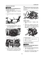
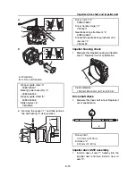
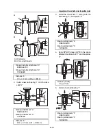
Trim rod adjustment
1.
Push the unlock button on the remote con-
trol transmitter so that power is supplied to
the ECM and the trim position is set to the
N position.
2.
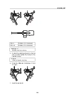
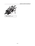
Disconnect the shift rod joint “1”.
3.
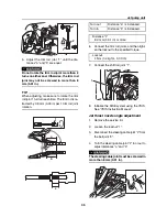
Disconnect the trim rod joints “1”.
4.
Loosen the locknut “2”.
Jet pump unit bolt (M10
×
45 mm) “1”
40 Nm (4.0 kgf·m, 29.5 ft·lb)
Jet pump unit bolt (M8
×
18 mm) “2”
17 Nm (1.7 kgf·m, 12.5 ft·lb)
2
1
1207B
1
3
1
2
3
LT
572
LT
572
2
1
Spout hose clamp “2”
2.5 Nm (0.25 kgf·m, 1.84 ft·lb)
Steering cable joint nut “7”
7 Nm (0.7 kgf·m, 5.2 ft·lb)
7
3
5
4
1
1
2
6
1
Содержание Waverunner VXS VX1800
Страница 1: ...SERVICE MANUAL WaveRunner VXS VX1800 F2W VXR VX1800A F2W F2W 28197 ZU 11 ...
Страница 12: ...How to use this manual 1 7 UP Upside YDIS Yamaha Diagnostic System Abbreviation Description ...
Страница 32: ...Technical tips 1 27 Trolling Neutral Neutral Reverse Engine stopped Condition Lever Reverse gate ...
Страница 40: ...Technical tips 1 35 MEMO ...
Страница 163: ...Oil separator tank and oil pan 5 72 3 4 4 4 4 4 9 4 1 5 6 10 11 7 2 3 8 ...
Страница 179: ...Crankcase connecting rod and piston 5 88 Crankcase bolt 1 10 Nm 1 0 kgf m 7 4 ft lb 12 11 10 4 2 6 8 9 3 1 5 7 1 ...
Страница 180: ...Crankcase connecting rod and piston 5 89 MEMO ...
Страница 196: ...6 15 Impeller drive shaft and impeller duct Impeller duct bolt 5 40 Nm 4 0 kgf m 29 5 ft lb 1 3 2 5 5 5 5 4 3 ...
Страница 204: ...6 23 Intermediate housing Intermediate housing bolt 2 17 Nm 1 7 kgf m 12 5 ft lb 1 2 3 ...
Страница 205: ...Intermediate housing 6 24 MEMO ...
Страница 251: ...Indication system 7 44 MEMO ...
Страница 253: ...8 Hull and hood Rear section 8 31 Spout installation 8 33 Reboarding step installation VXR 8 33 Deck and hull 8 34 ...
Страница 278: ...8 25 Exhaust system 6 Install the band Rubber hose clamp 2 3 5 Nm 0 35 kgf m 2 58 ft lb ...
Страница 290: ...Deck and hull 8 37 MEMO ...
Страница 312: ...Engine unit troubleshooting 9 21 MEMO ...
Страница 313: ...A Appendix Wiring diagram A 1 How to use the wiring diagram A 1 VXS VXR A 2 ...
Страница 317: ......
Страница 318: ...Mar 2015 CR E ...

