9-3
YDIS
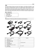
When the communication cable is used to connect a computer to the ECM, the ECM record data
can be saved and viewed on the computer.
The saved ECM record data can also be viewed offline.
TIP:
To display the data and graphs, see the YDIS (Ver. 2.20) Instruction Manual.
8.
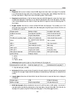
Logging:
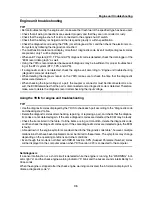
While the computer and engine are not connected, record “Engine Monitor” data using
the adapter interface.
9.
Engine record:
Displays the number of times the engine was started during the period when en-
gine control was deactivated.
10.
SCU initial learning:
The RiDE system needs to be initialized again if any of the jet pump unit com-
ponent or RiDE motor has been replaced (or removed).
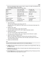
Engine speed
Ref. TPS voltage*2
No-wake mode
APS 1
Ref. APS voltage*3
Low-RPM mode
APS 2
Target TPS voltage for ISC*4
Engine shut-off switch
Steering sensor
Engine stop mode
Main relay
TPS 1
Engine start mode
ETV relay
TPS 2
SW-activated engine stop
mode*5
Thermoswitch
Intake air pressure
OTS mode
Oil pressure switch
Battery voltage
Cruise assist mode
WARNING
Target TPS voltage*1
Reverse mode
ETV limit
*1. Target TPS voltage
This item shows the target output voltage of the TPS.
This value is the control voltage that the ECM requires to set the target opening angle of the
throttle valve.
*2. Reference TPS voltage
This item shows the criterion output voltage of the TPS.
This value is used to detect the TPS output voltage during engine operation.
*3. Reference APS voltage
This item shows the criterion output voltage of the APS.
This value is used to detect the APS output voltage when the throttle lever is opened.
*4. Target TPS voltage for Idle Speed Control
ECM controls the engine idle speed by using the throttle valve attached to the TPS.
This target voltage is used by the ECM to achieve the target opening angle of the throttle
valve at the engine idle speed.
*5. Engine stop mode with switch
Содержание Waverunner VXS VX1800
Страница 1: ...SERVICE MANUAL WaveRunner VXS VX1800 F2W VXR VX1800A F2W F2W 28197 ZU 11 ...
Страница 12: ...How to use this manual 1 7 UP Upside YDIS Yamaha Diagnostic System Abbreviation Description ...
Страница 32: ...Technical tips 1 27 Trolling Neutral Neutral Reverse Engine stopped Condition Lever Reverse gate ...
Страница 40: ...Technical tips 1 35 MEMO ...
Страница 163: ...Oil separator tank and oil pan 5 72 3 4 4 4 4 4 9 4 1 5 6 10 11 7 2 3 8 ...
Страница 179: ...Crankcase connecting rod and piston 5 88 Crankcase bolt 1 10 Nm 1 0 kgf m 7 4 ft lb 12 11 10 4 2 6 8 9 3 1 5 7 1 ...
Страница 180: ...Crankcase connecting rod and piston 5 89 MEMO ...
Страница 196: ...6 15 Impeller drive shaft and impeller duct Impeller duct bolt 5 40 Nm 4 0 kgf m 29 5 ft lb 1 3 2 5 5 5 5 4 3 ...
Страница 204: ...6 23 Intermediate housing Intermediate housing bolt 2 17 Nm 1 7 kgf m 12 5 ft lb 1 2 3 ...
Страница 205: ...Intermediate housing 6 24 MEMO ...
Страница 251: ...Indication system 7 44 MEMO ...
Страница 253: ...8 Hull and hood Rear section 8 31 Spout installation 8 33 Reboarding step installation VXR 8 33 Deck and hull 8 34 ...
Страница 278: ...8 25 Exhaust system 6 Install the band Rubber hose clamp 2 3 5 Nm 0 35 kgf m 2 58 ft lb ...
Страница 290: ...Deck and hull 8 37 MEMO ...
Страница 312: ...Engine unit troubleshooting 9 21 MEMO ...
Страница 313: ...A Appendix Wiring diagram A 1 How to use the wiring diagram A 1 VXS VXR A 2 ...
Страница 317: ......
Страница 318: ...Mar 2015 CR E ...

