2-9
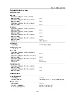
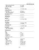
Electrical technical data
Thermo sensor
Input voltage
4.75–5.25 V
Resistance at 0°C (32°F)
24.0–37.1 k
Ω
Resistance at 100°C (212°F)
0.87–1.18 k
Ω
Engine temperature sensor
Input voltage
4.75–5.25 V
Resistance at 20°C (68°F)
54.2–69.0 k
Ω
Resistance at 100°C (212°F)
3.12–3.48 k
Ω
Intake air temperature sensor
Input voltage
4.75–5.25 V
Resistance at 0°C (32°F)
5.4–6.6 k
Ω
Resistance at 80°C (176°F)
0.29–0.39 k
Ω
Intake air pressure sensor
Input voltage
4.75–5.25 V
TPS
TPS 1 output voltage with the throttle lever fully
closed
0.45–0.55 V
TPS 2 output voltage with the throttle lever fully
open
4.60–4.70 V
TPS output voltage difference
1.9–2.1 V
Throttle valve opening angle with the throttle
lever fully closed
2–8°
Throttle valve opening angle with the throttle
lever fully open
More than 70°
Input voltage
4.75–5.25 V
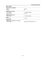
APS
APS 1 output voltage with the throttle lever
fully closed
0.68–0.74 V
APS 2 output voltage with the throttle lever
fully closed
0.68–0.74 V
APS 1 output voltage with the throttle lever
fully open
3.95–4.15 V
APS 2 output voltage with the throttle lever
fully open
3.95–4.15 V
APS output voltage difference
0.1 V or less
APS 1 input voltage
4.75–5.25 V
APS 2 input voltage
4.75–5.25 V
APS full close switch input voltage
4.75–5.25 V
RPS
RPS 1 output voltage with the RiDE lever fully
closed
0.68–0.74 V
RPS 2 output voltage with the RiDE lever fully
closed
0.68–0.74 V
RPS 1 output voltage with the RiDE lever fully
open
3.95–4.15 V
RPS 2 output voltage with the RiDE lever fully
open
3.95–4.15 V
Содержание Waverunner VXS VX1800
Страница 1: ...SERVICE MANUAL WaveRunner VXS VX1800 F2W VXR VX1800A F2W F2W 28197 ZU 11 ...
Страница 12: ...How to use this manual 1 7 UP Upside YDIS Yamaha Diagnostic System Abbreviation Description ...
Страница 32: ...Technical tips 1 27 Trolling Neutral Neutral Reverse Engine stopped Condition Lever Reverse gate ...
Страница 40: ...Technical tips 1 35 MEMO ...
Страница 163: ...Oil separator tank and oil pan 5 72 3 4 4 4 4 4 9 4 1 5 6 10 11 7 2 3 8 ...
Страница 179: ...Crankcase connecting rod and piston 5 88 Crankcase bolt 1 10 Nm 1 0 kgf m 7 4 ft lb 12 11 10 4 2 6 8 9 3 1 5 7 1 ...
Страница 180: ...Crankcase connecting rod and piston 5 89 MEMO ...
Страница 196: ...6 15 Impeller drive shaft and impeller duct Impeller duct bolt 5 40 Nm 4 0 kgf m 29 5 ft lb 1 3 2 5 5 5 5 4 3 ...
Страница 204: ...6 23 Intermediate housing Intermediate housing bolt 2 17 Nm 1 7 kgf m 12 5 ft lb 1 2 3 ...
Страница 205: ...Intermediate housing 6 24 MEMO ...
Страница 251: ...Indication system 7 44 MEMO ...
Страница 253: ...8 Hull and hood Rear section 8 31 Spout installation 8 33 Reboarding step installation VXR 8 33 Deck and hull 8 34 ...
Страница 278: ...8 25 Exhaust system 6 Install the band Rubber hose clamp 2 3 5 Nm 0 35 kgf m 2 58 ft lb ...
Страница 290: ...Deck and hull 8 37 MEMO ...
Страница 312: ...Engine unit troubleshooting 9 21 MEMO ...
Страница 313: ...A Appendix Wiring diagram A 1 How to use the wiring diagram A 1 VXS VXR A 2 ...
Страница 317: ......
Страница 318: ...Mar 2015 CR E ...

