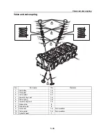
Valve and valve spring
5-50
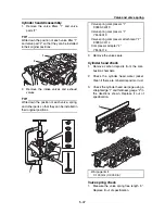
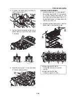
3.
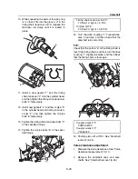
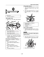
Insert the special service tool “1” into the
valve guide “2”, and then ream the valve
guide “2”.
TIP:
• Turn the special service tool “1” clockwise to
ream the valve guide “2”.
• Do not turn the special service tool “1” coun-
terclockwise when removing the tool.
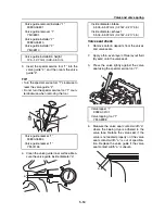
4.
Clean the valve guide inner surface. Mea-
sure the valve guide inside diameter “a”.
Valve seat check
1.
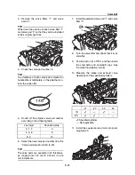
Remove carbon deposits from the valves
and valve seats.
2.
Apply a thin, even layer of blue layout fluid
(Dykem) onto the valve seat.
3.
Press the valve lightly against the valve
seat using the special service tool “1”.
4.
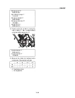
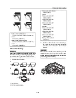
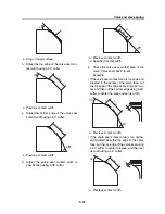
Measure the valve seat contact width “a”
where the blueing dye is adhered to the
valve face. Reface the valve seat if the
valve is not seated properly or if the valve
seat contact width “a” is out of specifica-
tion. Replace the valve guide if the valve
seat contact width “a” is uneven.
Valve guide remover/installer “1”
90890-06801
Valve guide remover “1”
YB-06801
Valve guide installer “2”
90890-06810
Valve guide installer “2”
YB-06810
Valve guide installation height
12.3–12.7 mm (0.48–0.50 in)
Valve guide reamer “1”
90890-06804
Valve guide reamer “1”
YM-01196
1
2
a
Inside diameter-intake
5.504–5.522 mm (0.2167–0.2174 in)
Inside diameter-exhaust
5.504–5.522 mm (0.2167–0.2174 in)
Valve lapper “1”
90890-04101
Valve lapping tool “1”
YM-A8998
1
a
Содержание Waverunner VXS VX1800
Страница 1: ...SERVICE MANUAL WaveRunner VXS VX1800 F2W VXR VX1800A F2W F2W 28197 ZU 11 ...
Страница 12: ...How to use this manual 1 7 UP Upside YDIS Yamaha Diagnostic System Abbreviation Description ...
Страница 32: ...Technical tips 1 27 Trolling Neutral Neutral Reverse Engine stopped Condition Lever Reverse gate ...
Страница 40: ...Technical tips 1 35 MEMO ...
Страница 163: ...Oil separator tank and oil pan 5 72 3 4 4 4 4 4 9 4 1 5 6 10 11 7 2 3 8 ...
Страница 179: ...Crankcase connecting rod and piston 5 88 Crankcase bolt 1 10 Nm 1 0 kgf m 7 4 ft lb 12 11 10 4 2 6 8 9 3 1 5 7 1 ...
Страница 180: ...Crankcase connecting rod and piston 5 89 MEMO ...
Страница 196: ...6 15 Impeller drive shaft and impeller duct Impeller duct bolt 5 40 Nm 4 0 kgf m 29 5 ft lb 1 3 2 5 5 5 5 4 3 ...
Страница 204: ...6 23 Intermediate housing Intermediate housing bolt 2 17 Nm 1 7 kgf m 12 5 ft lb 1 2 3 ...
Страница 205: ...Intermediate housing 6 24 MEMO ...
Страница 251: ...Indication system 7 44 MEMO ...
Страница 253: ...8 Hull and hood Rear section 8 31 Spout installation 8 33 Reboarding step installation VXR 8 33 Deck and hull 8 34 ...
Страница 278: ...8 25 Exhaust system 6 Install the band Rubber hose clamp 2 3 5 Nm 0 35 kgf m 2 58 ft lb ...
Страница 290: ...Deck and hull 8 37 MEMO ...
Страница 312: ...Engine unit troubleshooting 9 21 MEMO ...
Страница 313: ...A Appendix Wiring diagram A 1 How to use the wiring diagram A 1 VXS VXR A 2 ...
Страница 317: ......
Страница 318: ...Mar 2015 CR E ...

