5-41
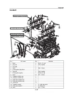
Camshaft
3.
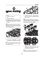
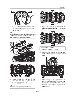
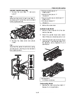
Remove the valve lifters “1” and valve
pads “2”.
TIP:
Write down the position of each valve lifter “1”
and valve pad “2” so that they can be installed
in their original positions.
4.
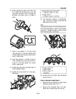
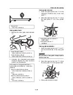
Check the valve pad number “a”.
TIP:
The thickness of each valve pad is marked in
hundredths of millimeters on the side that con-
tacts the valve lifter.
5.
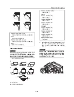
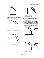
Round off the original valve pad number
according to the following table.
6.
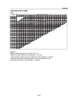
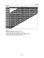
Select the new valve pad number from the
“Valve pad selection table” (5-43).
TIP:
The valve pads are available in 23 thickness-
es, ranging from 1.20 mm to 2.30 mm in 0.05
mm increments.
7.
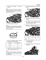
Install the selected valve pad “1” and valve
lifter “2”.
8.
Turn the valve lifter and check that it turns
smoothly.
9.
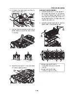
Position piston #1 at TDC, and then install
the camshafts and camshaft caps. See
“Camshaft installation” (5-38).
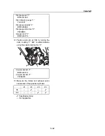
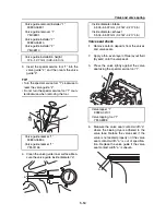
10. Measure the intake and exhaust valve
clearances of the specified cylinders.
: Specified cylinder
—: Not applicable
11. Install the special service tools into spark
plug hole #4.
Last digit
Rounded value
0, 1, 2
0
4, 5, 6
5
8, 9
10
1
2
148
a
#1
#2
#3
#4
IN
—
—
EX
—
—
2
1
2
1
3
Содержание Waverunner VXS VX1800
Страница 1: ...SERVICE MANUAL WaveRunner VXS VX1800 F2W VXR VX1800A F2W F2W 28197 ZU 11 ...
Страница 12: ...How to use this manual 1 7 UP Upside YDIS Yamaha Diagnostic System Abbreviation Description ...
Страница 32: ...Technical tips 1 27 Trolling Neutral Neutral Reverse Engine stopped Condition Lever Reverse gate ...
Страница 40: ...Technical tips 1 35 MEMO ...
Страница 163: ...Oil separator tank and oil pan 5 72 3 4 4 4 4 4 9 4 1 5 6 10 11 7 2 3 8 ...
Страница 179: ...Crankcase connecting rod and piston 5 88 Crankcase bolt 1 10 Nm 1 0 kgf m 7 4 ft lb 12 11 10 4 2 6 8 9 3 1 5 7 1 ...
Страница 180: ...Crankcase connecting rod and piston 5 89 MEMO ...
Страница 196: ...6 15 Impeller drive shaft and impeller duct Impeller duct bolt 5 40 Nm 4 0 kgf m 29 5 ft lb 1 3 2 5 5 5 5 4 3 ...
Страница 204: ...6 23 Intermediate housing Intermediate housing bolt 2 17 Nm 1 7 kgf m 12 5 ft lb 1 2 3 ...
Страница 205: ...Intermediate housing 6 24 MEMO ...
Страница 251: ...Indication system 7 44 MEMO ...
Страница 253: ...8 Hull and hood Rear section 8 31 Spout installation 8 33 Reboarding step installation VXR 8 33 Deck and hull 8 34 ...
Страница 278: ...8 25 Exhaust system 6 Install the band Rubber hose clamp 2 3 5 Nm 0 35 kgf m 2 58 ft lb ...
Страница 290: ...Deck and hull 8 37 MEMO ...
Страница 312: ...Engine unit troubleshooting 9 21 MEMO ...
Страница 313: ...A Appendix Wiring diagram A 1 How to use the wiring diagram A 1 VXS VXR A 2 ...
Страница 317: ......
Страница 318: ...Mar 2015 CR E ...

