7-37
Remote control system
Remote control system
Remote control transmitter check
1.
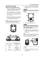
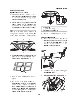
Push the unlock button “a”. The buzzer
sounds 2 times, and then check that the
“UNLOCK” indicator light “b” comes on.
2.
Push the unlock button “a” for more than 4
seconds. The buzzer sounds 3 times, and
then check that the “L-MODE” indicator
light “c” comes on.
3.
Push the lock button “d”. The buzzer
sounds once, and then check that the “UN-
LOCK” indicator light “b” goes off.
TIP:
While the engine is running, input from the re-
mote control transmitter is not received.
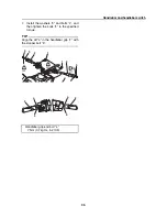
4.
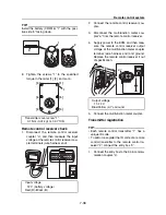
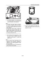
Loosen the screws “1” in the order [1], [2],
and so on, and then remove the transmit-
ter cover “2”.
Do not touch the internal parts except the
battery.
5.
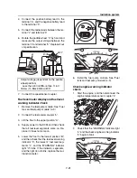
Remove the battery (CR2016) “1”.
Do not touch the battery directly using your
hands. Use a pair of non-conductive twee-
zers to replace the battery.
6.
Measure the battery voltage. Replace the
remote control transmitter battery if below
specification.
TIP:
Refer to local hazardous waste regulations
when disposing of transmitter batteries.
7.
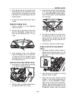
Install the battery (CR2016) “1” and trans-
mitter cover “2”.
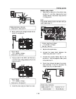
Number of beeps
Yamaha Security
System mode
1 beep
Lock
2 beeps
Unlock
(normal mode)
3 beeps
L-MODE
(low-rpm mode)
a
d
b
c
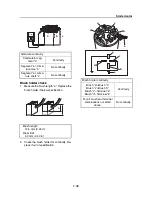
Rating
3 V
[4]
[1]
[5]
[3]
[2]
[6]
1
2
1
Содержание Waverunner VXS VX1800
Страница 1: ...SERVICE MANUAL WaveRunner VXS VX1800 F2W VXR VX1800A F2W F2W 28197 ZU 11 ...
Страница 12: ...How to use this manual 1 7 UP Upside YDIS Yamaha Diagnostic System Abbreviation Description ...
Страница 32: ...Technical tips 1 27 Trolling Neutral Neutral Reverse Engine stopped Condition Lever Reverse gate ...
Страница 40: ...Technical tips 1 35 MEMO ...
Страница 163: ...Oil separator tank and oil pan 5 72 3 4 4 4 4 4 9 4 1 5 6 10 11 7 2 3 8 ...
Страница 179: ...Crankcase connecting rod and piston 5 88 Crankcase bolt 1 10 Nm 1 0 kgf m 7 4 ft lb 12 11 10 4 2 6 8 9 3 1 5 7 1 ...
Страница 180: ...Crankcase connecting rod and piston 5 89 MEMO ...
Страница 196: ...6 15 Impeller drive shaft and impeller duct Impeller duct bolt 5 40 Nm 4 0 kgf m 29 5 ft lb 1 3 2 5 5 5 5 4 3 ...
Страница 204: ...6 23 Intermediate housing Intermediate housing bolt 2 17 Nm 1 7 kgf m 12 5 ft lb 1 2 3 ...
Страница 205: ...Intermediate housing 6 24 MEMO ...
Страница 251: ...Indication system 7 44 MEMO ...
Страница 253: ...8 Hull and hood Rear section 8 31 Spout installation 8 33 Reboarding step installation VXR 8 33 Deck and hull 8 34 ...
Страница 278: ...8 25 Exhaust system 6 Install the band Rubber hose clamp 2 3 5 Nm 0 35 kgf m 2 58 ft lb ...
Страница 290: ...Deck and hull 8 37 MEMO ...
Страница 312: ...Engine unit troubleshooting 9 21 MEMO ...
Страница 313: ...A Appendix Wiring diagram A 1 How to use the wiring diagram A 1 VXS VXR A 2 ...
Страница 317: ......
Страница 318: ...Mar 2015 CR E ...

