SonTek RS5 User Manual (August 2020) 107
the ADP approaches a vertical bank. Because the velocity processing normally requires
all 4 beams, if one beam hits a bank before the other beams, it will cut off profiles at a
shallower location to avoid data contamination, causing a sloping shoring of data, like
the example shown in Figure 94.
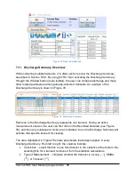
Figure 94. Sloping profile data as one beam hits a vertical wall
Using this data example, the beam switching tool can remove the bad beam from the
dataset and use a 3-beam solution to calculate velocities. Opening the beam switching
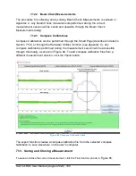
tool will show the dialog in Figure 95.
Figure 95. Beam Switching Dialog
From the beam switching dialog, the user can see what beam is hitting an obstacle. In
the example in Figure 95, the beam depth plot (middle plot) shows obvious interference
from Beam 2 (blue) near the left bank and Beam 4 (yellow) near the right bank. The
user can create two different beam switching “sections” to correct these areas.


