V5 series inverter
51
4-2. Function code description
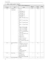
4-2-1. Basic operating function parameters (Group P0)
P0.00
Control mode selection
Range: 0~1
0
0: V/F control
1: Open loop vector control
P0.01
Frequency setting channel selection
Range: 1~8
0
0: Panel analog potentiometer setting
1: and keys on the panel
You can set the reference frequency via and keys on the panel.
2: Keyboard digital setting
Initial frequency is the value of P0.02, change the value in P0.02 by operate panel.
3: Terminal UP/DOWN
Initial frequency is the value of P0.02, set the frequency via terminal UP/DOWN.
4: Serial port (remote control)
Initial frequency is the value of P0.02, set the frequency via serial port.
5: VI analog input (VI
-
GND)
The frequency is set by analog voltage input via terminal VI, the input voltage range is DC 0~10V. The relationship be-
tween frequency and VI is decided by parameters P1.00~P1.05.
6: CI analog input (CI
-
GND)
The frequency is set by analog voltage/current of terminal CI and the input range is DC 0~10V (jumper JP3 select “V”
side), DC: 4~20mA (jumper JP3 select “A” side). The relationship between frequency and CI input is decided by parameter
P1.06~P1.10.
7: Pulse input (PLUSE)
The frequency is set by pulse input via pulse terminal (can only be input via terminal X6). The relationship between fre-
quency and PLUSE input is decided by parameters P1.11~P1.15.
8: Combination
Please refer to P3.00, set the frequency via the combination of each channel.
P0.02
Digital frequency setting
Range: Upper limit of frequncy~lower limit of frequency
50.00Hz
When the frequency is set in digital mode
(
P0.01
=
1, 2, 3, 4
)
, the value of P0.02 is the inverter’s initial frequency.
Содержание V5
Страница 1: ...Xinje Electronic Co Ltd VB3 VB5 V5 frequency inverter User manual No INV C 01 20081130 204 ...
Страница 4: ......
Страница 8: ......
Страница 42: ...V5 series inverter 34 Fig 3 12 Procedures of starting the inverter for the first time ...


