V5 series inverter
75
4-2-7. Fault recording parameters (Group P6)
P6.00
last fault record
Range: 0~23
0
P6.07
Last 2 fault record
Range: 0~23
0
P6.08
Last 3 fault record
Range: 0~23
0
P6.09
Last 4 fault record
Range: 0~23
0
P6.10
Last 5 fault record
Range: 0~23
0
P6.11
Last 6 fault record
Range: 0~23
0
0: no fault
1~17: E-01~E-17 fault, refer to chapter 5.
P6.01
Output frequency of last fault
Range: 0~upper limit of frequency
0
P6.02
Setting frequency of last fault
Range: 0~upper limit of frequency
0
P6.03
Output current of last fault
Range: 0~999.9A
0
P6.04
Output voltage of last fault
Range: 0~999V
0
P6.05
DC bus voltage of last fault
Range: 0~800V
0
P6.06
Module temperature of last fault
Range: 0~100
0
4-2-8. Close-loop control parameters (Group P7)
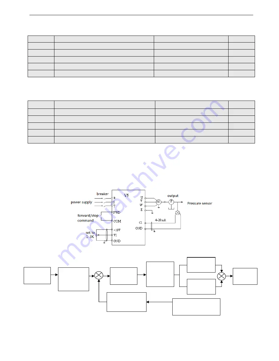
Analog feedback control system:
Pressure value is input in VI, and feedback value (4
~
20mA) of pressure sensor is input to inverter CI then pass through
the internal PI adjustor to form analog close-loop control system, as shown in Fig4-32.
Fig.4-32 Analog feedback control system with internal PI
Principle diagram of inverter’s internal PI adjustor is shown below:
+ +
-
+
Fig. 4-33 PI control principle diagram
The definition of close-loop value, feedback value, difference limit and proportion/integral parameter in Fig 4-33 are the
same to normal PI definition. Please refer to P7.01~P7.11. The relationship between preset value and expect feedback val-
ue is shown in Fig 4-34. The preset value is based on 10V; the feedback value is based on 20mA.
The aim of preset value adjustment and feedback value adjustment is to confirm the their relationship and size, as shown in
Close-loop
preset value
Preset
value
adjustment
(P7.06,P7.08)
Difference
limit (P7.13)
Close-loop
adjust feature
(P7.14)
Proportion
gain (P7.10)
Integral gain
(P7.11)
Feedback value ad-
just (P7.07, P7.09)
Close-loop
output
Close-loop feedback value
Содержание V5
Страница 1: ...Xinje Electronic Co Ltd VB3 VB5 V5 frequency inverter User manual No INV C 01 20081130 204 ...
Страница 4: ......
Страница 8: ......
Страница 42: ...V5 series inverter 34 Fig 3 12 Procedures of starting the inverter for the first time ...


