V5 series inverter
18
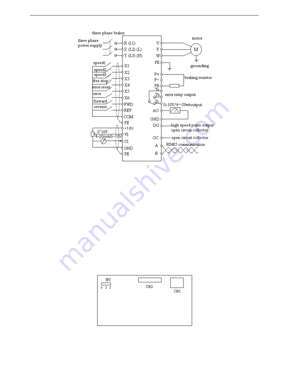
2-4. Basic running wiring
Note:
(1) P- terminal is only used in 5.5KW and larger inverters.
(2) L, N terminals are suitable for 220V single phase inverters.
(3) L1, L2, L3 terminals are suitable for VB5 series 0.75~3.7KW three phases types.
(4) VB5 series 0.75~3.7KW three phases have no digital input X5, analog input VI and digital output DO.
(5) VB3/VB5 series single phase have no X4~X6, VI, AO, DO, OC, P+, P-, PB.
(6) VB3 series 0.75~3.7KW three phases have no terminal X5, X6 and VI, DO, P+, P-, PB.
2-5. Setting and wiring of control circuit
2-5-1.Position and function of terminals and jumpers on control panel
Please open the front cover of inverter, there is the PCB board inside. The jumper is on the board.
0.4 ~0.75KW VB3 series inverter jumper position
Fig 2
-
4(a) jumper position on control board
Содержание V5
Страница 1: ...Xinje Electronic Co Ltd VB3 VB5 V5 frequency inverter User manual No INV C 01 20081130 204 ...
Страница 4: ......
Страница 8: ......
Страница 42: ...V5 series inverter 34 Fig 3 12 Procedures of starting the inverter for the first time ...


