V5 series inverter
55
P0.16
Acc/Dec time unit
Range: 0, 1
0
This function defines Acc/Dec time unit
0: second
1: minute
Note:
(1) This function is valid for all the Acc/Dec mode except jog running.
(2) Second unit is recommended.
P0.17
Acc time 1
Range: 0.1~6000.0
10.0
P0.18
Dec time 1
Range: 0.1~6000.0
10.0
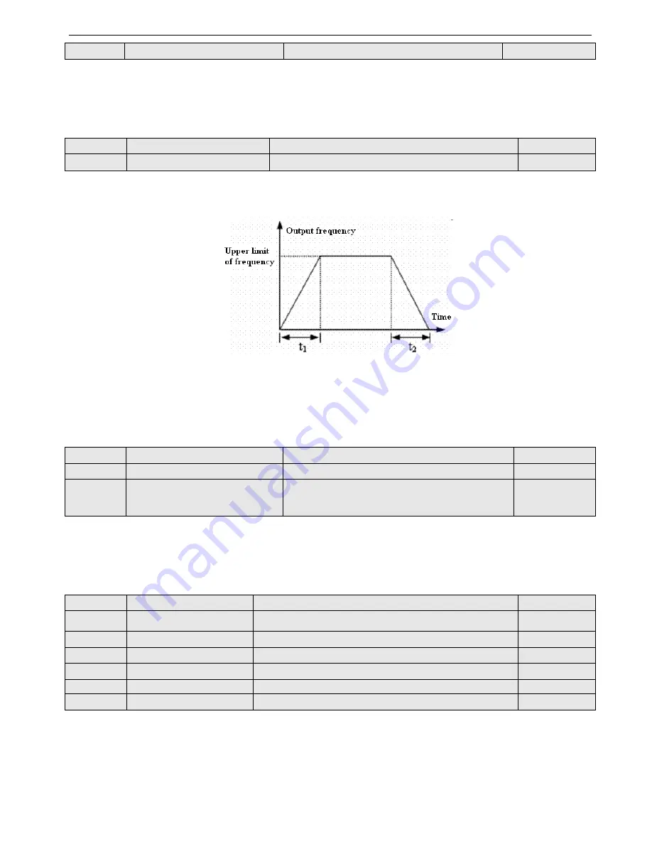
Acc time is the time accelerating from 0 Hz to highest frequency, see t
1
in Fig.4-6; Dec time is the time decelerating from
highest frequency to 0 Hz, see t
2
in Fig.4-6.
Fig.4-6
Acc/Dec time
Note
: (1) This series inverter defines seven kinds of Acc/Dec time. Here only defines Acc/Dec time 1, Acc/Dec time 2~7
are defined in P3.14~P3.25.
(2) Define the Acc/Dcc time unit in P0.16 (minute, second, default is second).
P0.19
Highest frequency
Range: lowest frequency~max output frequency
50.00Hz
P0.20
Lowest frequency
Range: 0.00Hz~highest frequency
0.00HZ
P0.21
Lowest frequency running mode
Range:
0: run with lowest frequency
1: stop
0
P0.19 and P0.20 define the upper and lower frequency, see Fig.4-2 FH(highest frequency) and FL(lowest frequency).
If the actual setting frequency is lower than lowest frequency, inverter will decelerate the output frequency. When it reach
the lowest frequency, if the lowest frequency running mode is 0, inverter will run with lowest frequency. If the lowest
frequency running mode is 1, inverter will decrease the output frequency to 0.
P0.22
V/F curve setting
Range: 0~4
0
P0.23
V/F frequency value F1
Range: 0.00~P0.25
0.00Hz
P0.24
V/F voltage valueV1
Range: 0~P0.26
0.0%
P0.25
V/F frequency value F2
Range: P0.23~P0.27
0.00Hz
P0.26
V/F voltage value V2
Range: P0.24~P0.28
0.0%
P0.27
V/F frequency value F3
Range: P0.25~P0.07 basic running frequency
0.00Hz
P0.28
V/F voltage value V3
Range: P0.26~ 100.0%
0.0%
This group of parameters defines the flexible V/F setting modes of this inverter to satisfy the requirement of different loads.
Four fixed curves and one user-defined curve can be selected in P0.22.
P0.22=0, V/F curve is constant torque curve, as shown in Fig.4-7 curve 0.
P0.22=1, V/F cuve is 1.2 powers torque-reducing curve, as shown in Fig. 4-7 curve 1.
P0.22=2, V/Fcuve is 1.7 powers torque-reducing curve, as shown in Fig.4-7 curve 2.
P0.22=3, V/Fcuve is 2.0 powers torque-reducing curve, as shown in Fig.4-7 curve 3.
Содержание V5
Страница 1: ...Xinje Electronic Co Ltd VB3 VB5 V5 frequency inverter User manual No INV C 01 20081130 204 ...
Страница 4: ......
Страница 8: ......
Страница 42: ...V5 series inverter 34 Fig 3 12 Procedures of starting the inverter for the first time ...


