


75
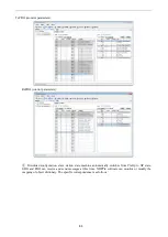
Bit4-6 (operation mode specific):
Bit
Name
Value
Definition
4
new set-point
0 -> 1
Trigger the positioning action start and setting value
update.
Get a new position decision task (607Ah (Target
position), 6081h (Profile velocity)
5
change set immediately
0
Complete the currently running positioning action.
1
Interrupt the current positioning action and start the
downward positioning action immediately
6
absolute/ relative
0
607Ah (Target position) is processed as absolute
position.
1
607Ah (Target position) is processed as relative
position.
Please do not change the acceleration and deceleration (*) during motor operation.
If you change the acceleration and deceleration, please change bit4 (new set point) from 0 - > 1 after the motor
stops.
6083h (Profile acceleration)
6084h (Profile deceleration)
60C5h (Max acceleration)
60C6h (Max deceleration)
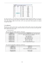
3.
Status word (6041h) <PP control mode function>
Index
Sub-
Index
Name/Description
Range
Date
Type
Access
PDO
Op-
mode
6041
h
00h
Statusword
0~65535
U16
ro
TxPDO
All
Indicates the servo driver status.
Bit information
15
14
13
12
11
10
9
8
r
oms
ila
oms
rm
r
set- point
acknowledge
Target
Reached
7
6
5
4
3
2
1
0
w
sod
qs
ve
f
oe
so
rsto
r = reserved (Not corresponding) w = warning
sod = switch on disabled
oms = operation mode specific qs = quick stop
(control mode based on bit) ve = voltage enabled
ila = internal limit active f = fault
oe = operation enabled
rm = remote so = switched on
rtso = ready to switch on
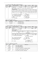
bit12, 10 (operation mode specific):
Bit
Name
Value
Definition
10
target reached
0
halt=0 (normal): positioning not completed
halt=1 (stop as halt): axis is decelerating
1
halt=0 (normal): positioning completed
halt=1 (stop as halt): axis stop (axis speed is 0)
12
set-point
acknowledge
0
new-setpoint is 0 and the buffer is empty after executing the
action of the current target position
1
The new location task data is put into the buffer. The buffer
is not empty
Содержание DF3E Series
Страница 1: ... 1 DF3E series servo driver User manual Wuxi Xinje Electric Co Ltd Data No SF3 01 20210607 1 0 ...
Страница 23: ...15 Fixed installation Bending radius 5 D 5 D Note D represents the finished product cable diameter ...
Страница 121: ...113 2 select jog setting or manual setting to configure the inertia estimation trip 3 Set the auto tuning interface ...
Страница 126: ...118 4 click ok to estimate the inertia 5 set the auto tuning parameters ...
Страница 128: ...120 7 Wait for the end of the auto tuning ...
Страница 132: ...124 8 The upper device starts to send pulses wait the completion of auto tuning 9 Auto tuning is finished click ok ...
Страница 184: ...176 Appendix 8 Torque speed characteristic curve ...