


4-23
5. Xerographic
Section 4 Disassembly/Assembly/Adjustment
5.1.1 Drum Unit Replacement
NOTE
:
•
Be careful of the following in handling
the Drum Unit:
a. Place the removed Unit on a flat
surface.
b. Keep the Drum away from direct
strong light. Put a protective cover
over it.
c. Do not rotate the Drum anti --
clockwise.
e. Do not touch the Drum surface with
your bare hand(s).
Removal
1. Power off the machine and disconnect the
Power Plug.
2. Open the Front Cover and then the machine.
3. (Fig. 3): Remove the Drum Unit.
➀
. Push Lock Lever.
➁
. Pull out Drum Unit.
(Fig. 1)
Installation
1. Install the Drum Unit securely. Its improper
installation will cause J3 to be displayed.
Put the plug ID into the socket.
2. Perform the Basic Copy Quality Adjustment.
…………………………………………….. (5.1.4)
Reference
••••
Drum Unit
a. When replacing the Drum,
replace the whole Drum Unit.
(It is impossible to replace the
Drum alone.) The Drum Unit
contains the Drum Cleaning
Blade, Film Seal and Charge
Corotron.
b. Max. Copy Output Quantity
When the Drum Unit is shipped
out of the plant, the max. copy
output quantity is set on
ID as below:
M/C
Type
Max. Copy Output
Qty on ID
(Initial Value)
5915
50,000
c. “Drum Cartridge(Unit)
Replacement” Display
Remaining
Copy
Output Qty
Drum
Cartridge
Replacement
Display
Status
Code
Copy
5,000
ON
--
Possible
500
Flash
--
Possible
0
Flash
(continuously)
J7-1
Not
possible
When the cartridge reaches
the end of its service life, the
Replace copy cartridge lamp
flashes and the Copy Quantity
display shows “J7”.
d. Remaining Copy Output Qty
The remaining copy output
quantity is stored in EPROM
incorporated into the Drum
Unit. You can check on the
remaining copy output quantity
in [81] of “Performance Spec.”
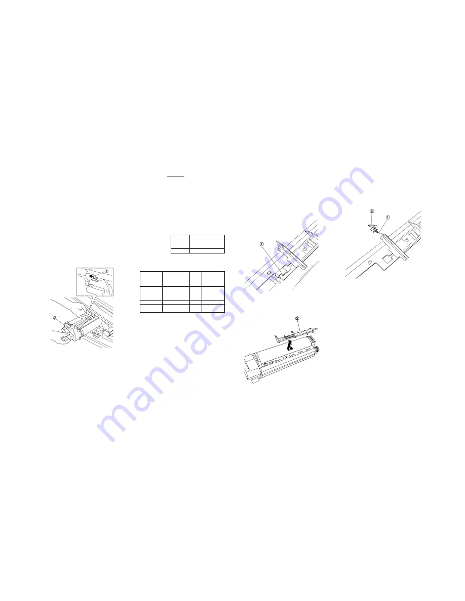
5.1.2 Drum Finger Replacement
Removal
1. Power off the machine and disconnect the
Power Plug.
2. Open the Front Cover and then the machine.
3. Remove the Drum Unit......………......... (5.1.1)
4. (Figs. 1 & 2): Remove the Finger Assembly.
➀
. (Fig. 1): Remove Stopper preventing the
disengagement of Finger Assy.
(Fig. 1)
➁
. (Fig. 2): Remove Finger Assy from Bracket
by sliding it to the front of Drum Unit.
(Fig. 2)
5. (Fig. 3): Remove the Drum Finger.
WARNING
:
•
Take care not to hurt yourself in
removing the Finger. Its tip is
sharp.
➀
. Remove Spring.
➁
. Remove Drum Finger.
(Fig. 3)
Installation
1. Perform the installation in the reverse order of
removal.
CAUTION
:
•
Check that the Drum Finger tip is
not damaged.
•
Take care not to damage the Drum
surface in installing the Finger
Assy.
•
Install the Stopper in the proper
direction referring to Fig. 1.
Содержание 5915
Страница 1: ...XEROX 5915 SERVICE MANUAL Issued by Overseas Technical Group Xerox of Shanghai Limited 7th July 200 ...
Страница 4: ...Section 1 Service Procedure ...
Страница 6: ...1 2 Section 1 Service Procedure 1 1 Precautions Intentional bank page ...
Страница 9: ...Section 2 Troubleshooting ...
Страница 12: ...2 3 Section 2 Troubleshooting Intentional blank page ...
Страница 21: ...2 12 Section 2 Troubleshooting 2 3 Level1 Troubleshooting 2 3 Level 1 Troubleshooting 2 3 1 Level 1 F I P ...
Страница 35: ...Section 4 Disassembly Assembly Adjustment ...
Страница 37: ...4 2 Section 4 Disassembly Assembly Adjustment Intentional blank page ...
Страница 76: ...Section 5 Parts List ...
Страница 110: ...Section 6 GENERAL ...
Страница 123: ...Section 7 Wiring Data ...
Страница 124: ...7 1 Contents Section 7 Wiring Data Section 7 Wiring Data Plug Jack List 7 2 Connector Configuration 7 5 ...
Страница 128: ...7 5 Connector Configuration Section 7 WIRING DATA TOP VIEW Fig 1 TOP VIEW Fig 2 REAR VIEW Fig 3 MAIN MOTOR MAIN PWB ...
Страница 130: ...7 7 Connector Configuration Section 7 WIRING DATA R H VIEW A A DETAILS TOP VIEW Fig 6 Fig 7 ...
Страница 131: ...7 8 Section 7 Wiring Data Connector Configuration TOP VIEW Fig 8 BASE FRAME TOP VIEW Fig 9 ...
Страница 132: ...Section 9 BSD Block Schematic Diagram ...
Страница 135: ...9 3 1 1 STANDBY POWER Section 9 BSD Block Schematic Diagram ...
Страница 136: ...9 4 Section 9 BSD Block Schematic Diagram 1 1 STANDBY POWER ...
Страница 137: ...9 5 1 1 STANDBY POWER Section 9 BSD Block Schematic Diagram ...
Страница 138: ...9 6 Section 9 BSD Block Schematic Diagram 2 MODE SELECTION MACHINE RUN CONTROL START PRINT POWER ...
Страница 139: ...9 7 3 1 OPTICS Section 9 BSD Block Schematic Diagram ...
Страница 141: ...9 9 4 PAPER SUPPLYING AND TRANSPORTATION Section 9 BSD Block Schematic Diagram ...
Страница 143: ...9 11 5 XEROGRAPHICS COPY TRANSPORTATION AND FUSING Section 9 BSD Block Schematic Diagram ...


