14
2.
For the installer
2.3.4 Prior to installation
Move the boiler to its definitive installation position and use the set screws to align it inclined slightly upwards towards
the rear.
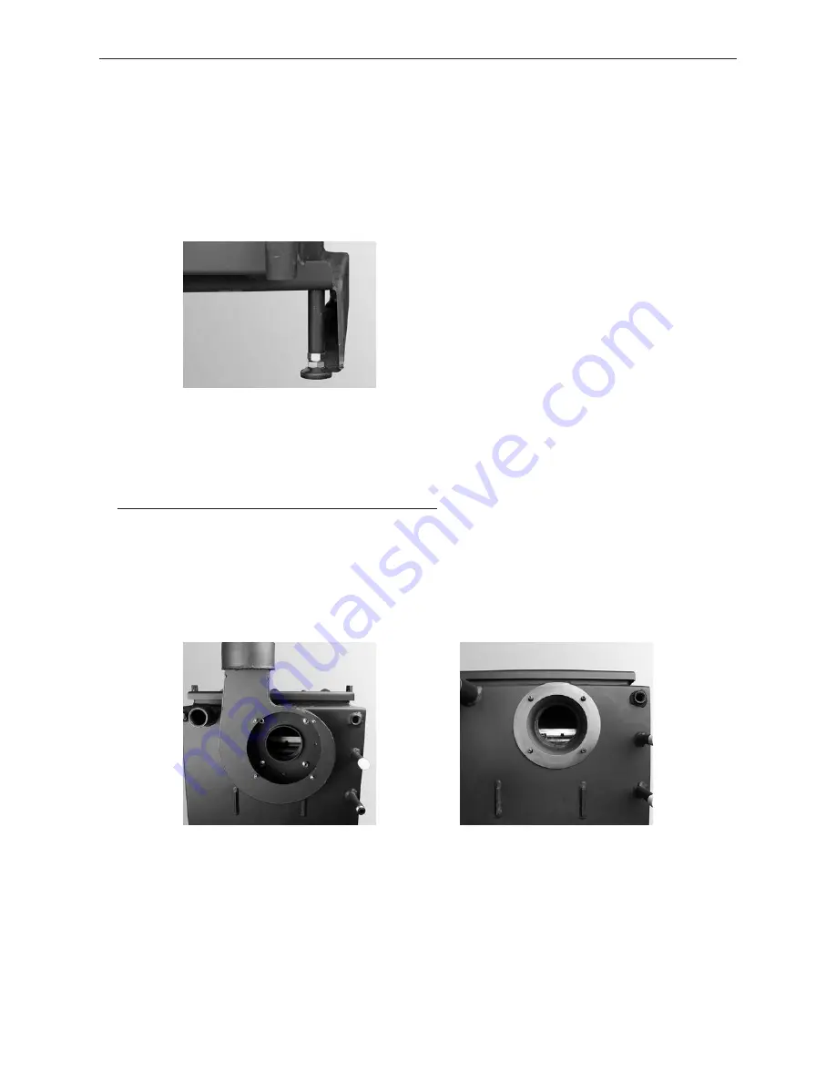
If it is not possible to level the unit using only the rear set screws. 2 additional set screws can be installed at the front
– Fig. 7.
The cladding door and the boiler doors are designed for door catches on either the left or right. Standard delivery
always includes a door catch on the left. The catches on the cladding door and boiler doors must be on the same side.
2.3.5 Installing the flue connection adapter
– Only for LogWIN with flue connection adapter (accessories)
Standard installation of the blower housing is directly on the boiler – Fig. 8 → flue connection at top.
With the adapter (accessories). the blower housing is located outside the cladding – Fig. 11. The flue connection is
steplessly adjustable from left to right – Fig. 10.
– Unscrew 4 interior nuts in the blower housing (Fig. 8) and remove the housing. Do not remove the seal – Fig. 9.
Fig. 7
Installing of 2 set screws in the front
Fig. 8
Blower housing directly on boiler –
standard
Fig. 9
Seal on boiler


