background image

Kunststoffschweißtechnik

 Electric 

diagrams 

Chapter 10 

07.02.13 

Working Instructions WIDOS 25000 mobile  

Page 90 of 116 


Содержание 25000 mobile

Страница 1: ...ingen Heimerdingen Fax 49 7152 9939 40 website www widos de email info widos de Headquarters D 71254 Ditzingen Heimerdingen Country court Stuttgart HRB 200973 Managing director Jürgen Dommer Working Instructions Translation Heating element butt welding machine WIDOS 25000 mobile Keep for further use ...

Страница 2: ...tory No Place of working Order of spare parts and after sales service Address of manufacturer WIDOS W Dommer Söhne GmbH Einsteinstrasse 5 D 71254 Ditzingen Heimerdingen Phone 49 7152 99 39 0 Fax 49 7152 99 39 40 info widos de www widos de Address of the subsidiary companies WIDOS WIDOS GmbH W Dommer Söhne AG An der Wiesenmühle 15 St Gallerstr 93 D 09224 Grüna Sachsen CH 9201 Gossau Phone 49 371 8 ...

Страница 3: ...ce team in the factory or in our subsidiary companies We will help you with pleasure According to our interest to continuously improve our products and working instructions we kindly ask you to inform us about problems and defects which occur in exercise Thank you Structure of the working instructions This manual is arranged in chapters which belong to the different using phases of the machine Due...

Страница 4: ...n 13 2 5 Information about safety precautions 13 2 6 Instructions for the staff 13 2 7 Maintenance and inspection repair 14 2 8 Dangers while handling the machine 14 2 9 Dangers caused by electric energy 14 2 10 Specific dangers 15 2 10 1 Danger of stumbling over electric hydraulic wires 15 2 10 2 Dangers caused by the hydraulics 15 2 10 3 Danger of combustion by heating element and welding area 1...

Страница 5: ... cabinet 36 4 13 1 Fuses in the switch cabinet 37 4 13 1 1 Additional keyboard for diagnosis test 38 5 STARTING AND OPERATING 39 5 1 Safety indications 39 5 2 Remote control 40 5 2 1 Meaning of control levers 1 6 within mode select 1 6 41 5 2 2 Emergency stop switch 42 5 2 2 1 Emergency stop switch with key 42 5 2 3 Accumulator for operator console 42 5 3 How to switch on the machine 43 5 3 1 Lab ...

Страница 6: ...o vent the hydraulic cylinders 56 8 8 Protect machine parts against corrosion 56 8 9 Cutter 57 8 10 How to lubricate the guidings for the leveling legs 57 8 11 Vacuum device optional 58 8 12 Disposal 58 9 TRANSPORT 59 9 1 How to detach the flexible clamping rings 59 9 2 How to fix the cutter in the machine 61 9 3 How to swing in the heating element 61 9 4 How to remove the carriage 62 9 5 How to s...

Страница 7: ... is removable for welding the machine is leveled by four leveling legs All use going beyond is not purpose oriented The manufacturer is not responsible for damages caused by misuse The risk is held only by the user Also part of the purpose oriented use is respecting all the indications of the working instructions and performing the inspection and maintenance work 1 2 Safety measures In case of wro...

Страница 8: ...leg flat Left clamping tools Switch cabinet Pipe cutter Heating element Hydraulic pump Right clamping tools Remote control Pipe clampers Front leveling leg Machine illumination floodlight Main cylinder for welding Slewing cylinder for opening closing the clamping tools Abdominal belt Cylinder for transverse motion of the pipes Cylinder for transverse motion of the pipes Carriage ...

Страница 9: ...igatory to wear ear protection When using the named pipe materials and when welding below 260 C no toxicant damp arises Ambient conditions in the welding area take care for cleanness no dust at the welding area If secured by an appropriate measurement that allowed conditions for welding are indicated it is possible to work in any outside temperature condition as far as the welder is not constraine...

Страница 10: ...nsulation system IP 54 Max working pressure of pump appr 250 bar Working pressure 0 250 bar adjustable 1 5 1 4 Heating element Power 57 6 kW Voltage 400V 10 Current 252 A 10 Frequency 50 Hz Outside Ø 2600 mm Inside Ø 1600 mm Surface anti stick coated with PTFE plastic film 1 5 1 5 Pipe cutter Hydraulic motor OMR 80 Speed appr 21 rpm Inlet pressure 175 bar factory set 1 5 1 6 Vacuum device AF 14 op...

Страница 11: ...Lumen including illuminant 0853218 mobile 1 7 Wear parts tools and accessories Following tools and accessories are part of the delivery 2 Q Cut Insert 151 2 45 80 6 Q Cut infeed plate 4G 151 2 800 4E with clamping screw 3212012 259 50 l Hydraulic oil 10 Heating cartridge Ø 16 x 550 mm 800 W 400 V Al 1 5 m 6 Temperature sensor PT 1000 H09086 2 Heating element relay PTFE fiber glass 0 25 mm 1 each A...

Страница 12: ...es on goods This symbol means a possible dangerous situation due to hot surfaces The disrespect of these indications may conduct to heavy burns respectively to self ignition or even fire This symbol means a possible dangerous situation by moving parts of the machine The disrespect of these indications may cause heavy crushing of parts of the body resp damages of parts of the machine This symbol me...

Страница 13: ...equired for personal safety is to be provided by the owner All available safety equipment is to be inspected regularly 2 5 Information about safety precautions The working instructions have to be permanently kept at the place of use of the machine They are to be at the operator s disposal at any time and without effort In addition to the manual the common valid and the local accident protection ru...

Страница 14: ...ver dangers for the operator or other persons standing nearby may occur Also material damages are possible The machine may only be used according to the purpose oriented usage in safety technical impeccable status Disturbances which may affect the safety of the machine must be cleared immediately 2 9 Dangers caused by electric energy Only skilled persons are allowed to work at electrical appliance...

Страница 15: ...y hydraulic oil squirting out Damaged hydraulic hoses have to be immediately replaced Make a visual inspection of the hydraulic hoses before each work beginning The hydraulic oil is inedible 2 10 3 Danger of combustion by heating element and welding area You can burn yourself inflammable materials can be ignited The heating element temperature is heated up to more than 250 C Do not leave the heati...

Страница 16: ...lothes by the cutter You can cut yourself or even get broken bones the knives are very sharp Only wear clothes tight to the body Do not wear rings or jewellery during the work If necessary wear a hair net Do not touch the knives Wear gloves while you replace the knives If you are working within the machine protect the area of the knives at the cutter e g by plastic film cardboard cloths in order t...

Страница 17: ...thout permission of the manufacturer Machine parts which are not in a perfect condition are to be replaced immediately Only use original WIDOS spare and wear parts In case of purchase orders please always state the machine number 2 12 Warranty and liability Fundamentally our General Sales and Delivery Conditions are valid They are at the owner s disposal latest when signing the contract Guarantee ...

Страница 18: ...g element is inserted and the pipes are pressed against the heating element under defined adjusting pressure This process is called adjusting After the prescribed bead height being reached pressure is reduced the heating time begins The function of this time is to heat up the pipe ends After expiration of the heating time the slides are opened the heating element is moved out of machine in the bas...

Страница 19: ...erating and indicating elements 4 1 Basic machine with carriage No Denomination Function 1 Basic machine For cutting and welding the pipes workpieces 2 Rear leveling leg 2 pieces For aligning the machine with or without carriage 3 Carriage For transporting the machine may be removed 4 Front leveling leg flat version For aligning the machine with or without carriage 5 Front leveling leg For alignin...

Страница 20: ...ther are driven together to the right left 7 Right clamping ring are opened shut together are driven together to the left right 8 Pressure gauge analogue attached to each clamping ring showing the current clamping pressure 9 Switch cabinet with main switch emergency stop and power sockets for illumination power sockets for vacuum and SD card drive different interfaces and fuses 6 7 8 9 10 14 12 11...

Страница 21: ...eveling legs free couplings e g for pipe brackets 4 2 1 Reducer inserts and assembling aid optional In order to install the reducer inserts use the assembling aid Lift the front reducer inserts at the second drill hole from above and the rear reducer inserts at the third drill hole from above the clamping rings are hanging now in mounting position The reducer inserts are laterally guided on the cl...

Страница 22: ...ng by two bolts for reducer insert Six drill holes are available for fixing Mounting of the rear reducer inserts Open both clamping tools Bring the rear reducer insert into the machine Move the reducer insert by a crane in a way that it rests according to the radius of the clamping ring and the lateral lugs rest against the clamping ring from the outside Fix the reducer insert and the clamping rin...

Страница 23: ...ector L1 into machine optional M83 Drive ejector L2 out of machine optional M84 Drive ejector L2 into machine optional Hydraulic block 2 No Denomination Function No Denomination Function M35 Heating element right tear off initial position M36 Heating element right tear off working direction M61 Right clamping tool open M62 Right clamping tool shut M65 Release clamping tool R1 M66 Fix clamping tool...

Страница 24: ...pen M26 Heating element locking shut M29 Release heating element position M111 Additional valve V6 inactive M112 Additional valve V6 active M113 Not assigned 1 inactive M114 Not assigned 1 active M115 Not assigned 2 inactive M116 Not assigned 2 active Hydraulic block 5 No Denomination Function No Denomination Function M40 Cutter M41 Drive cutter out of machine M42 Drive cutter into machine M45 Cut...

Страница 25: ...m is mounted above it facilitates the tearing off of the heated pipes during change over The heating element is driven back and forth and into welding area initial position If necessary you may mount one further optional heating plate to the existing one in order to weld pipes up to OD 1600 mm In this case disconnect the interfaces from the existing heating plate and put the plugs onto the holders...

Страница 26: ...speed is factory set If necessary you may modify the speeds for driving in and out see chapter 7 4 4 2 Heating element zones The heating element features two heating plates Each heating plate has two heating zones Lower ring bolt with plate bolt and hexagon socket screw View without guard plate Hydraulic block 4 for heating element Front heating plate Rear heating plate Heating zone 1 front upper ...

Страница 27: ...ng direction The head of the cutter features cutting blades on both sides they cut the pipe from inside to outside You may also adjust the blades to the pipe inner diameter by the portable screwdriver Suggestion Drive the blades towards the pipe inner diameter at a short distance and start cutting by the remote control afterwards While setting the blades onto the pipe inner diameter make sure that...

Страница 28: ... screwdriver before you swing them in or out short arms into initial position in order that the clamping tools do not collide while inserting the arms You may only swing the cutter in or out if the color sensor detects the red color This guarantees that the cutter does not collide with the base frame while swinging it Make sure that the label is not removed Label for color detection red Color sens...

Страница 29: ...e pipe into the machine It is indispensable to fix the machine to the ground by the leveling legs during welding in order that the machine cannot tilt e g while opening the clamping rings If necessary you should support the flat leveling leg by e g pieces of wood Driving up and downwards is done by Mode select no 1 and by Level left front Level right front You may swing the front leveling leg to t...

Страница 30: ...to the ground by the leveling legs during welding in order that the machine cannot tilt e g while opening the clamping rings In case the machine is transported you may swing the rear leveling leg to the front side 4 8 How to remove the carriage You may remove the carriage before welding e g in order to avoid unnecessary lifting of the pipes Drive the leveling legs out Remove the ring bolts on both...

Страница 31: ...How to fix clamping tools If necessary you may fix the clamping rings to the left or right and weld with only one pair of the clamping rings View from above Put the fixing plate to the top of the base frame and tighten the fixing plate from below by hexagon socket screws M 24 Insert the spacer block between support angle and fixing plate and tighten the three parts by hexagon socket screws M 24 Pu...

Страница 32: ...ing ring by a crane with the flange showing inwards Caution danger of tilting Hold the stub end holder by the crane thus long until the holder is within the shut clamping ring and clamped by the clamping ring upper part In case the rear side of the flange rests against the rear clamping ring you may shut the clamping tool carefully and clamp the inner clamping ring afterwards In order to adjust th...

Страница 33: ...gainst the stub end holder and clamp it by the claws 4 10 1 How to put the stub end holder onto the transport rack Hinge the stub end holder e g at a crane open the clamping tool and lift the stub end holder out of the machine In order to put it into the transport rack bring the stub end holder towards the rack and necessarily put the flange behind the beam arrow in order to avoid slipping Then ca...

Страница 34: ... part and lock it by the spring plug Connect the hydraulic hoses with the free couplings to the basic machine on the left and or on the right side Afterwards move the block cylinder out until the pipe jack has the necessary length Select level 6 by Mode select and push levers V3 V6 according to the selected connector to in order to move the cylinder out or to in order to move the cylinder back aga...

Страница 35: ...e chip tank while evacuating a large part of the cutting chips will be collected in the tank the rest in the chip bag Connect the connecting cable to the power socket CEE 16 A at the switch cabinet Activate deactivate the vacuum using the switch at the motor Please learn handling and maintenance of the vacuum device AF14 from the separately enclosed working instructions of the Felder company Empty...

Страница 36: ...ating zone 1 L1 L3 Control lamp 3 pieces for heating zone 1 phase 1 3 Heating zone 2 L1 L3 Control lamp 3 pieces for heating zone 2 phase 1 3 Heating zone 3 L1 L3 Control lamp 3 pieces for heating zone 3 phase 1 3 Heating zone 4 L1 L3 Control lamp 3 pieces for heating zone 4 phase 1 3 Handle with switch cabinet lock Open shut the switch cabinet Caution Hand over key only to authorized personnel Em...

Страница 37: ...uit breaker B32A fuse heating element zone 3 F24 3 pieces circuit breaker B32A fuse heating element zone 4 F80 3 pieces circuit breaker B16A fuse vacuum device G10 Soft starter for hydraulic pump K101 Contactor lightings Q1 Main switch 100 125A Q2 Contactor emergency stop hydraulic pump Q3 Contactor emergency stop heating element zone 1 Q4 Contactor emergency stop heating element zone 2 Q5 Contact...

Страница 38: ...e the same temperature In case one temperature is extremely differing from the others this means e g that a heating cartridge is damaged Pressure You may drive a pressure using the remote control in the manual mode In case you want to keep this pressure press Pressure the display shows Display 2 nd line Pressure d 0 4 a 0 4 0 Indication of nominal pressure d and actual pressure a ADC You may view ...

Страница 39: ...e from wetness and humidity According to VDE 0100 the use on construction sites is only allowed with a power distributor with a FI security protective switch Check the oil level of the hydraulic system before each starting of the control unit in order to avoid damages on the pump If necessary add hydraulic oil of the quality HLPD 32 The heating element surfaces must be clean especially non greasy ...

Страница 40: ...rol the different 6 functions of the control lever 1 6 Display shows status of the machine several values may be indicated Joystick Open drives machine tables apart P1 drives tables onto welding pressure of regulator P1 P2 drives tables onto welding pressure of regulator P2 P3 drives tables onto welding pressure of regulator P3 Cutter motor to adjust the driving speed min max of the cutter Termina...

Страница 41: ...g Cutter in working position lock unlock Lever 5 Unassigned valve Not assigned Lever 6 Cutter rotate Rotate cutter and Mode select 4 Lever 1 Heater pos Drive heating element into position left right Lever 2 Heater in Heating element welding position drive in drive out Lever 3 Heater locking Heating element in working position lock unlock Lever 4 Heater off L Left pipes from heating element tear of...

Страница 42: ... danger of combustion Fire risk for the workpieces The heating element is hot and cools down very slowly 5 2 2 1 Emergency stop switch with key The emergency stop with key is mounted to the switch cabinet You may remove the key in both positions In case you are working within the machine you may press the emergency stop and remove the key afterwards This warrants that nobody may activate the machi...

Страница 43: ...isplay alternates with Display 2nd line WIDOS 25000 SPA 220 C 0 bar Main menu 5 3 1 Lab menu Display 2nd line WIDOS 25000 SPA 11 00 20 02 2012 Main menu Press Enter in the main menu in order to enter the lab menu Display 2nd line mat diam wall LAB0 000 00 0 Adjust material You may adjust the material by and Press Start for the next menu step Display 2nd line mat diam wall LAB0 0000 00 0 Adjust dia...

Страница 44: ...d Press Start confirm and go to the next parameter Display 2nd line t heat 220 s Adjust heating time You may adjust the heating time by and Press Start confirm and go to the next parameter Display 2nd line t cool SWP cool 10 10 00 00 N mm Adjust cooling time min You may adjust the cooling time and Press Start confirm and go to the next parameter Display 2nd line t cool SWP cool 10 10 00 00 N mm Ad...

Страница 45: ...t with a WICON program The card may not be bent opened overheated and become wet Please only use SD cards purchased from WIDOS We will not be liable for any cards from other manufactures 5 3 3 Read out WICON with USB card reader optional You may read out the welding data onto a PC by the USB card reader Remove the card from the SD card drive of the CNC aggregate Remove the rear cap and plug card a...

Страница 46: ... 0 0 15 34 3 0 0 0 0 0 0x0002 274 170 0 0 0 0 15 100 0 0 0 0 0 15 16 1 0 0 0 0 0 0x0002 274 168 0 0 0 0 15 100 0 0 0 0 0 15 16 1 0 0 0 0 0 0x0002 274 165 0 0 0 0 15 200 0 1 0 0 0 15 29 6 0 0 0 0 0 0x0002 275 166 0 0 0 0 15 200 0 0 1 0 0 15 12 2 0 0 0 0 0 0x0002 Temperature regulator 3 Temperature regulator 4 Bead up time Bead up pressure SWP bead up Nominal heating time Heating time Heating pressu...

Страница 47: ... area Do wear safety gloves as a protection against combustion The noise level exceeds 80 dB A while working with the machine especially during cutting of pipe ends Ear protection is obligatory during cutting You may be injured by cutting chips flying around Necessarily wear safety glasses during the cutting of the pipe ends The machine must always stand on the leveling legs for welding 6 1 How to...

Страница 48: ...utter Start turning the cutter only if no person and foreign objects are within the rotational area Do not touch the cutter in the area of the blades in any case Drive the pipes apart by pushing Joystick to Open Select Mode select level 3 Drive the cutter into lateral position between the clamped pipes by pushing Cutter pos to Swing the cutter into the working position by pushing Cutter in to Lock...

Страница 49: ...sation is done by clamping resp releasing the pipe tensioner even more In case you have made mismatch compensation you must repeat cutting Drive the pipes apart by pushing Joystick to Open 6 4 Drag pressure measurement Turn all pressure regulators to Min Display 2nd line WIDOS 25000 SPA 11 00 20 02 2012 Main menu Press Start in order to start welding Display 2nd line mat diam wall LAB0 000 00 0 Cu...

Страница 50: ...ivate another function button lever joystick so the pressure is deactivated again 6 6 Heating Select Mode select level 5 When the prescribed revolving bead has formed push the lever release pressure to thus starting the heating time Display 2nd line Heat t heat 000s 220 p curr 00 Indication of elapsed heating time Temperature and current pressure indication Select Mode select level 4 In order that...

Страница 51: ... End of welding Select Mode select level 5 When the cooling time has elapsed release the pressure from the welding cylinders by pushing Release pressure to Display 2nd line WIDOS 25000 SPA 11 00 20 02 2012 Main menu Select Mode select level 2 Release the pipe tighteners one after the other by pushing each lever Clamp L1 Clamp L2 Clamp L3 and Clamp L4 to Open both clamping tools by pushing the leve...

Страница 52: ... the diagnosis program Open the switch cabinet use the CNC keyboard for the adjustment Display 2nd line WIDOS 25000 SPA 11 00 20 02 2012 Main menu Press button Enter Press button Start several time until cursor is below diag Display 2nd line diag clk WICON param _ 10 18 Press button Enter If necessary first enter the security code using Enter Display 2nd line diag clk WICON param 0000 Enter diagno...

Страница 53: ...play 2nd line XXXX Forth value is displayed You may change the slow speed Change the numerical value using Enter Jump to the next value by Start Display 2nd line XXXX Fifth value is displayed You may change the fast speed Change the numerical value using Enter Then press Start several times until the basic menu appears Display 2nd line WIDOS 25000 CNC 20 02 2012 10 18 Machine type is displayed cur...

Страница 54: ...ol while working within the machine You do not step onto lines and motion elements Inform the operating personnel before the beginning of any maintenance and repair work Generally care for cleanness Handle the machine with care Immediately replace damaged parts take special care at electric parts The linear guides for heating element and planer must be cleaned every week e g with a brush Check the...

Страница 55: ...machine The used material and substances for cleaning the machine are to be properly handled and disposed of especially upon cleaning with solvents upon lubricating with oil and grease 8 5 How to check the hydraulic oil level for welding Before each starting up of the control unit check the oil level of the hydraulic unit in order to avoid damages There is an inspection glass at the front of the h...

Страница 56: ... from the basic machine Eliminate the cause of the air entrance Open the machine completely First unscrew the lower vent screw for closing Connect the transparent venting hose and insert it in the collecting vessel of the aggregate Close until there is no more air visible in the venting hose then tighten again the vent screw Close the machine completely Unscrew the lower vent screw for opening Con...

Страница 57: ...ting nipples at each arm Grease the cutter regularly monthly The cutting plate is fixed to the insert by clamping bolts Replace the cutting plates as soon as the cutting quality decreases Q Cut cutting plate 151 2 800 4E H13A and clamping bolt 3212012 259 8 10 How to lubricate the guidings for the leveling legs All four leveling legs feature lubricating nipples for lubricating the guiding axes Reg...

Страница 58: ...acuum performance decreases Release the clamping ring by the clamping lever then you may open the cap and empty the cutting chips Shut the clamping ring again after having emptied the tank Please learn the correct maintenance and care from the separately enclosed working instructions for the vacuum device AF14 8 12 Disposal At the end of the life time the machine has to be disposed of properly non...

Страница 59: ... g by a flat bed trailer you must Detach the flexible front clamping rings Fold the heating element Remove the carriage Swing in the leveling legs to the front sides 9 1 How to detach the flexible clamping rings In case the tables with the clamping rings have not been opened entirely drive the tables apart pushing Joystick to Open until the tables have reached their final position Lift the clampin...

Страница 60: ...s at the quick action couplings Loosen the grub screws by which the axes have been fixed Then remove the axes Detach the pan head screws at each cylinder for the clamping rings and remove both angles from the cylinder Now you may remove the front clamping rings Cylinder for opening and closing Quick action couplings Bracket Pan head screws Grub screw Axis ...

Страница 61: ...g lever Cutter in lock to 9 3 How to swing in the heating element Before you may swing in the heating element you must fix the cutter in the machine according to chapter 9 2 Drive the heating element in direction of the switch cabinet pushing Mode select level 4 a lever Heater pos to Fix the heating element in this position by pushing lever Heater locking to First detach the upper hexagon socket s...

Страница 62: ...he carriage as described in chapter 4 8 9 5 How to swing in the front leveling legs In order to transport the machine you may swing in the front leveling legs Drive the leveling leg upwards thus far that sufficient space is below the leg Detach the hexagon socket screws M 24 by which the locking bars have been fixed into the carriers Pull the locking bars to the front using the ring bolts arrow Fi...

Страница 63: ...winging the leveling leg make sure that the hydraulic lines do not get crushed 9 6 How to swing in the rear leveling leg In order to transport the machine e g in a container you may swing the rear leveling legs to the front side Drive the rear leveling leg completely upwards Pull the ring bolts 8 units leg out and swing the leg to the front side by 90 Secure the requested position by the ring bolt...

Страница 64: ... Einsteinstr 5 Phone 49 7152 9939 0 W Dommer Söhne GmbH D 71254 Ditzingen Heimerdingen Fax 49 7152 9939 40 website www widos de email info widos de 07 02 13 Working Instructions WIDOS 25000 mobile Page 64 of 116 10 Electric diagrams ...

Страница 65: ...Kunststoffschweißtechnik Electric diagrams Chapter 10 07 02 13 Working Instructions WIDOS 25000 mobile Page 65 of 116 ...

Страница 66: ...Kunststoffschweißtechnik Electric diagrams Chapter 10 07 02 13 Working Instructions WIDOS 25000 mobile Page 66 of 116 ...

Страница 67: ...Kunststoffschweißtechnik Electric diagrams Chapter 10 07 02 13 Working Instructions WIDOS 25000 mobile Page 67 of 116 ...

Страница 68: ...Kunststoffschweißtechnik Electric diagrams Chapter 10 07 02 13 Working Instructions WIDOS 25000 mobile Page 68 of 116 ...

Страница 69: ...Kunststoffschweißtechnik Electric diagrams Chapter 10 07 02 13 Working Instructions WIDOS 25000 mobile Page 69 of 116 ...

Страница 70: ...Kunststoffschweißtechnik Electric diagrams Chapter 10 07 02 13 Working Instructions WIDOS 25000 mobile Page 70 of 116 ...

Страница 71: ...Kunststoffschweißtechnik Electric diagrams Chapter 10 07 02 13 Working Instructions WIDOS 25000 mobile Page 71 of 116 ...

Страница 72: ...Kunststoffschweißtechnik Electric diagrams Chapter 10 07 02 13 Working Instructions WIDOS 25000 mobile Page 72 of 116 ...

Страница 73: ...Kunststoffschweißtechnik Electric diagrams Chapter 10 07 02 13 Working Instructions WIDOS 25000 mobile Page 73 of 116 ...

Страница 74: ...Kunststoffschweißtechnik Electric diagrams Chapter 10 07 02 13 Working Instructions WIDOS 25000 mobile Page 74 of 116 ...

Страница 75: ...Kunststoffschweißtechnik Electric diagrams Chapter 10 07 02 13 Working Instructions WIDOS 25000 mobile Page 75 of 116 ...

Страница 76: ...Kunststoffschweißtechnik Electric diagrams Chapter 10 07 02 13 Working Instructions WIDOS 25000 mobile Page 76 of 116 ...

Страница 77: ...Kunststoffschweißtechnik Electric diagrams Chapter 10 07 02 13 Working Instructions WIDOS 25000 mobile Page 77 of 116 ...

Страница 78: ...Kunststoffschweißtechnik Electric diagrams Chapter 10 07 02 13 Working Instructions WIDOS 25000 mobile Page 78 of 116 ...

Страница 79: ...Kunststoffschweißtechnik Electric diagrams Chapter 10 07 02 13 Working Instructions WIDOS 25000 mobile Page 79 of 116 ...

Страница 80: ...Kunststoffschweißtechnik Electric diagrams Chapter 10 07 02 13 Working Instructions WIDOS 25000 mobile Page 80 of 116 ...

Страница 81: ...Kunststoffschweißtechnik Electric diagrams Chapter 10 07 02 13 Working Instructions WIDOS 25000 mobile Page 81 of 116 ...

Страница 82: ...Kunststoffschweißtechnik Electric diagrams Chapter 10 07 02 13 Working Instructions WIDOS 25000 mobile Page 82 of 116 ...

Страница 83: ...Kunststoffschweißtechnik Electric diagrams Chapter 10 07 02 13 Working Instructions WIDOS 25000 mobile Page 83 of 116 ...

Страница 84: ...Kunststoffschweißtechnik Electric diagrams Chapter 10 07 02 13 Working Instructions WIDOS 25000 mobile Page 84 of 116 ...

Страница 85: ...Kunststoffschweißtechnik Electric diagrams Chapter 10 07 02 13 Working Instructions WIDOS 25000 mobile Page 85 of 116 ...

Страница 86: ...Kunststoffschweißtechnik Electric diagrams Chapter 10 07 02 13 Working Instructions WIDOS 25000 mobile Page 86 of 116 ...

Страница 87: ...Kunststoffschweißtechnik Electric diagrams Chapter 10 07 02 13 Working Instructions WIDOS 25000 mobile Page 87 of 116 ...

Страница 88: ...Kunststoffschweißtechnik Electric diagrams Chapter 10 07 02 13 Working Instructions WIDOS 25000 mobile Page 88 of 116 ...

Страница 89: ...Kunststoffschweißtechnik Electric diagrams Chapter 10 07 02 13 Working Instructions WIDOS 25000 mobile Page 89 of 116 ...

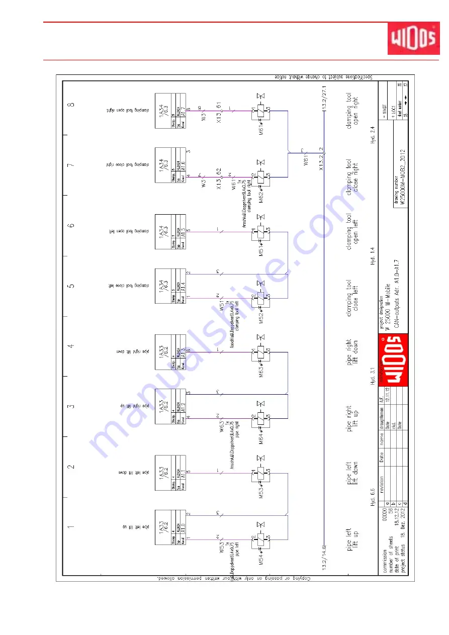
Страница 90: ...Kunststoffschweißtechnik Electric diagrams Chapter 10 07 02 13 Working Instructions WIDOS 25000 mobile Page 90 of 116 ...

Страница 91: ...Kunststoffschweißtechnik Electric diagrams Chapter 10 07 02 13 Working Instructions WIDOS 25000 mobile Page 91 of 116 ...

Страница 92: ...Kunststoffschweißtechnik Electric diagrams Chapter 10 07 02 13 Working Instructions WIDOS 25000 mobile Page 92 of 116 ...

Страница 93: ...Kunststoffschweißtechnik Electric diagrams Chapter 10 07 02 13 Working Instructions WIDOS 25000 mobile Page 93 of 116 ...

Страница 94: ...Kunststoffschweißtechnik Electric diagrams Chapter 10 07 02 13 Working Instructions WIDOS 25000 mobile Page 94 of 116 ...

Страница 95: ...Kunststoffschweißtechnik Electric diagrams Chapter 10 07 02 13 Working Instructions WIDOS 25000 mobile Page 95 of 116 ...

Страница 96: ...Kunststoffschweißtechnik Electric diagrams Chapter 10 07 02 13 Working Instructions WIDOS 25000 mobile Page 96 of 116 ...

Страница 97: ...Kunststoffschweißtechnik Electric diagrams Chapter 10 07 02 13 Working Instructions WIDOS 25000 mobile Page 97 of 116 ...

Страница 98: ...Kunststoffschweißtechnik Electric diagrams Chapter 10 07 02 13 Working Instructions WIDOS 25000 mobile Page 98 of 116 ...

Страница 99: ...Kunststoffschweißtechnik Electric diagrams Chapter 10 07 02 13 Working Instructions WIDOS 25000 mobile Page 99 of 116 ...

Страница 100: ...Kunststoffschweißtechnik Electric diagrams Chapter 10 07 02 13 Working Instructions WIDOS 25000 mobile Page 100 of 116 ...

Страница 101: ...Kunststoffschweißtechnik Electric diagrams Chapter 10 07 02 13 Working Instructions WIDOS 25000 mobile Page 101 of 116 ...

Страница 102: ...Kunststoffschweißtechnik Electric diagrams Chapter 10 07 02 13 Working Instructions WIDOS 25000 mobile Page 102 of 116 ...

Страница 103: ...Kunststoffschweißtechnik Electric diagrams Chapter 10 07 02 13 Working Instructions WIDOS 25000 mobile Page 103 of 116 ...

Страница 104: ...Kunststoffschweißtechnik Electric diagrams Chapter 10 07 02 13 Working Instructions WIDOS 25000 mobile Page 104 of 116 ...

Страница 105: ...Kunststoffschweißtechnik Electric diagrams Chapter 10 07 02 13 Working Instructions WIDOS 25000 mobile Page 105 of 116 ...

Страница 106: ...Kunststoffschweißtechnik Electric diagrams Chapter 10 07 02 13 Working Instructions WIDOS 25000 mobile Page 106 of 116 ...

Страница 107: ...Kunststoffschweißtechnik Electric diagrams Chapter 10 07 02 13 Working Instructions WIDOS 25000 mobile Page 107 of 116 ...

Страница 108: ...Kunststoffschweißtechnik Electric diagrams Chapter 10 07 02 13 Working Instructions WIDOS 25000 mobile Page 108 of 116 ...

Страница 109: ...Kunststoffschweißtechnik Electric diagrams Chapter 10 07 02 13 Working Instructions WIDOS 25000 mobile Page 109 of 116 ...

Страница 110: ...Kunststoffschweißtechnik Electric diagrams Chapter 10 07 02 13 Working Instructions WIDOS 25000 mobile Page 110 of 116 ...

Страница 111: ...Kunststoffschweißtechnik Electric diagrams Chapter 10 07 02 13 Working Instructions WIDOS 25000 mobile Page 111 of 116 ...

Страница 112: ...Kunststoffschweißtechnik Electric diagrams Chapter 10 07 02 13 Working Instructions WIDOS 25000 mobile Page 112 of 116 ...

Страница 113: ...Kunststoffschweißtechnik Electric diagrams Chapter 10 07 02 13 Working Instructions WIDOS 25000 mobile Page 113 of 116 ...

Страница 114: ...Kunststoffschweißtechnik Electric diagrams Chapter 10 07 02 13 Working Instructions WIDOS 25000 mobile Page 114 of 116 ...

Страница 115: ...Kunststoffschweißtechnik Electric diagrams Chapter 10 07 02 13 Working Instructions WIDOS 25000 mobile Page 115 of 116 ...

Страница 116: ...Kunststoffschweißtechnik Electric diagrams Chapter 10 07 02 13 Working Instructions WIDOS 25000 mobile Page 116 of 116 ...

Страница 117: ...Kunststoffschweißtechnik Electric diagrams Chapter 10 07 02 13 Working Instructions WIDOS 25000 mobile Page 117 of 116 ...

Страница 118: ...Kunststoffschweißtechnik Electric diagrams Chapter 10 07 02 13 Working Instructions WIDOS 25000 mobile Page 118 of 116 ...

Страница 119: ...Kunststoffschweißtechnik Electric diagrams Chapter 10 07 02 13 Working Instructions WIDOS 25000 mobile Page 119 of 116 ...

Страница 120: ...fers corresponds to the following norms and normative documents 1 DIN EN ISO 12100 1 and 2 replacement for DIN EN 292 part 1 and 2 Safety of machines basic terminology general guidelines for design 2 DIN EN 60204 1 Electric equipment of industrial machines 3 DIN EN ISO 4414 Safety specifications for fluid technical installations and components 4 DIN EN 60555 DIN EN 50082 DIN EN 55014 Electro magne...

Отзывы: