page 3 – 20
AM-55 / Sep 2015
A M - 5 5 G U I
In most programming situations the optimum setting of the coupling controls will likely
be somewhere between ‑1.0dB and ‑3dB for bands ABOVE the key band and ‑2.0dB to
‑6dB for bands BELOW the key band. Decoupling the Leveller’s bands beyond ‑6dB can
allow their gains to “wander” too much, causing unnatural spectral buildup on some
material. Therefore the maximum decoupling is 6dB.
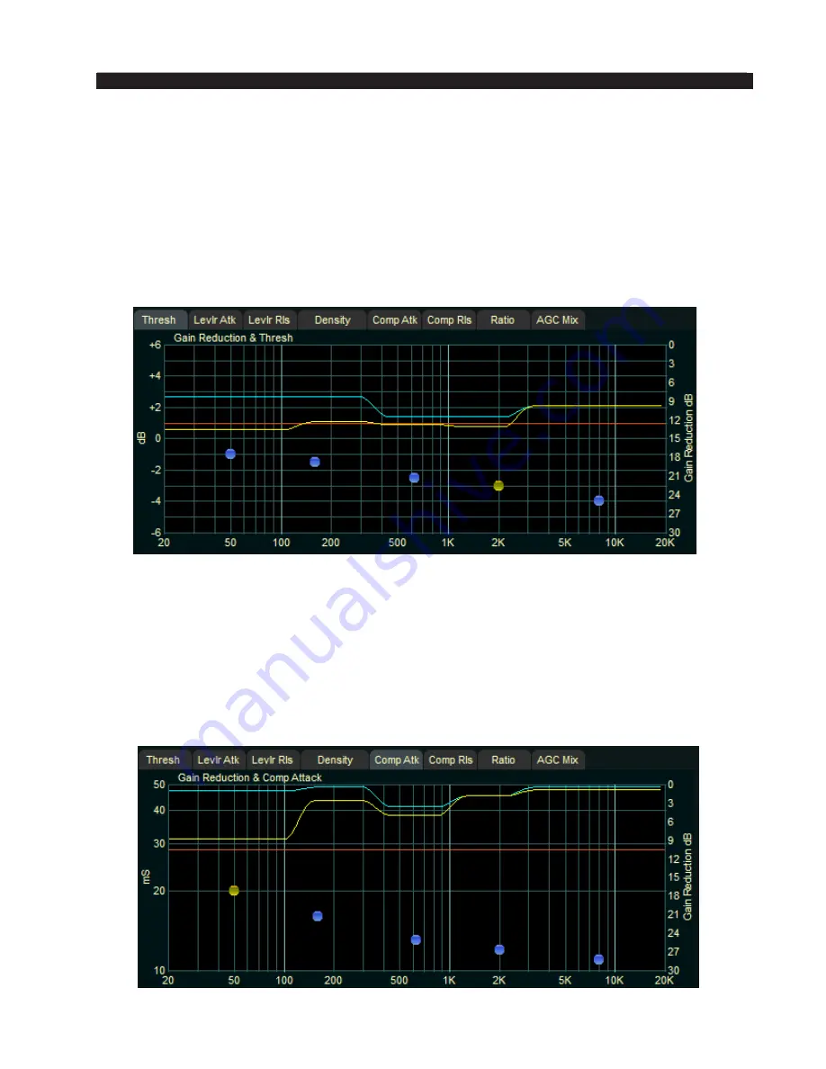
Each band has a compression threshold control which affects the operating threshold
of the Leveller and Compressor and that control is labeled Thresh in the graphic.
The lower region of the GUI allows the user to change the threshold and timing of the
five band leveller and compressor. It also has options for compression ratio and mixer output.
For more information on how to use the button controls, please see page 3‑8 of this Chapter.
The scale on the left side of the grid shows values of the five dots as it relates to the
option that is chosen, which can be selected by clicking on the tabs above the grid. In the
example above, the
Thresh (threshold) control is chosen and the scale on the left shows the
threshold level. If you were, to say, select Comp Atk
(compressor attack), you would see
the left scale change to show the timing values in milliseconds (ms) of the compressor as
shown below.
Multiband Leveller Dynamic Displays Menu


