background image

ActiveScale™ P100 Support Guide

74

identical, adding two scale up kits simultaneously results in link-local IP address 
conflicts.

Warning: 

Components in the scale up kit might have newer firmware than your 

existing components have. This procedure does not upgrade or downgrade any 
firmware.

Warning: 

If a scale up/out job is already in progress, wait until the current job is 

complete.

Warning: 

Do not start a log collection job while a scale up job is running.

1. Power up all components in the scale up kit.
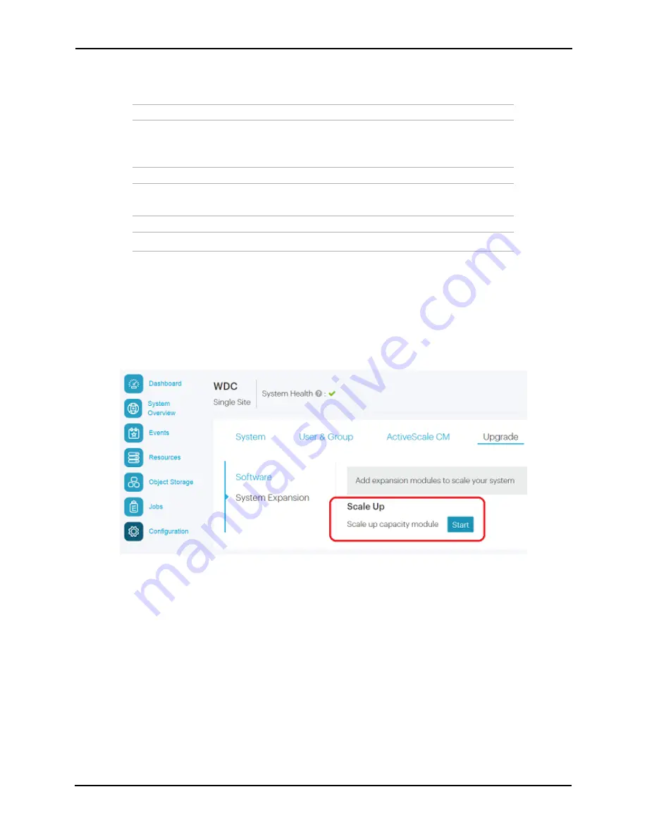
2. Start the scale up wizard. 

a. Click 

Configuration

 > 

Upgrade

.

b. In the 

System Expansion

 section, scroll down to 

Scale Up

.

c. Click 

Start

Figure 5-2. Starting a single site scale up 

Содержание ActiveScale P100

Страница 1: ...22 4 Storing the World s Data www wdc com ActiveScale P100 Support Guide January 2020 Publication 1ET0364 5 5 2 D 3 3...

Страница 2: ...ming or services in your country Technical information about this product is available by contacting your local Western Digital product representative or on the Internet at https portal wdc com Suppor...

Страница 3: ...1 3 System Node specification summary 20 2 2 System Interconnect 20 2 2 1 System Interconnect component identification 20 2 2 1 1 System Interconnect front and rear view 21 2 2 1 2 QSFP ports 21 2 2 1...

Страница 4: ...Replacing System Interconnect fans 41 3 2 1 1 Removing a System Interconnect fan 41 3 2 1 2 Installing a System Interconnect fan 42 3 2 2 Replacing System Interconnect PSUs 42 3 2 2 1 Removing a Syste...

Страница 5: ...e 1U mounting kit 61 4 System cabling 64 4 1 Reading cable labels 65 4 2 Cabling map 66 4 3 User provided cables 69 5 Installing scale up kits 70 5 1 Unpacking scale up kits 71 5 2 Installing scale up...

Страница 6: ...Replaceable part for mounting kits 120 A 3 Replaceable parts for Storage Nodes 120 A 4 Replaceable parts for System Interconnects 120 A 5 Replaceable parts for System Nodes 121 A 6 Upgrade kits 121 B...

Страница 7: ...ActiveScale P100 Support Guide 5 C 2 3 Electrostatic discharge 135 C 2 4 Power connections 135 C 2 5 Power cords 136 C 2 6 Rackmountable systems 136 C 2 7 Safety and service 136 Contact Us 138...

Страница 8: ...view 48 Table 3 17 2 5 inch drive replacement overview 51 Table 3 18 Storage Node PSU replacement overview 52 Table 3 19 Storage Node replacement overview 53 Table 3 20 3U mounting kit replacement ove...

Страница 9: ...ActiveScale P100 Support Guide List of tables 7 Table B 7 480 GB solid state drive specification summary 128 Table C 8 Country standards for safety 132 Table C 9 Product EMC immunity compliance 132...

Страница 10: ...2 17 With standoffs 29 Figure 2 18 Flush 29 Figure 3 19 Removing a drive 34 Figure 3 20 Scalar Node PSU handle and latch release 35 Figure 3 21 SFP transceiver removal 36 Figure 3 22 SFP transceiver i...

Страница 11: ...its found 81 Figure 5 11 Scale up Selecting a rack 81 Figure 5 12 Scale up Summary of scan 82 Figure 5 13 Scale up Applying network settings 82 Figure 5 14 Scale up Notification of job in progress 83...

Страница 12: ...ch system the new System Expansion Node is attached to 113 Figure 7 9 System Expansion Node Summary of scan 114 Figure 7 10 System Expansion Node Click Proceed to apply network settings 115 Figure 7 1...

Страница 13: ...1 1 ActiveScale P100 product overview This section provides an overview of the ActiveScale P100 system Topics ActiveScale P100 identification on page 12 System specification summary on page 14 Availab...

Страница 14: ...age using 14 TB HDD s Multi site systems can achieve a maximum storage capacity of either 19 44 PB raw using 10 TB HDDs 23 328 PB raw using 12 TB HDDs 27 216 PB raw using 14 TB HDDs Note 12 TB HDDs re...

Страница 15: ...4 Single scale up kit Storage Node CN 6 5 Double scale up kit Storage Node CN 6 6 System Expansion Node SEN 31 1 Maximum amount per ActiveScale P100 System Expansion Nodes are sold individually Table...

Страница 16: ...three additional nodes Power requirements typical maximum N A Base configuration 1 85 to 2 03 kW Base 1 configuration 3 23 to 3 54 kW Base 2 configuration 4 61 to 5 05 kW Scale Up kit 1 38 to 1 51 kW...

Страница 17: ...System Expansion Node kits System Expansion Node kits provide one additional System Node for your ActiveScale system Additional System Nodes allow you to increase system performance with your current...

Страница 18: ...2 Component overview This section provides an overview of each component in the ActiveScale P100 Topics System Node on page 17 System Interconnect on page 20 Storage Node on page 24 Pull out Tabs on...

Страница 19: ...in multiples of three The three System Nodes are clustered and the services and databases they run must have a minimum membership present in order to function Figure 2 2 System Node 2 1 1 System Node...

Страница 20: ...s Figure 2 6 System Node LEDs and buttons Table 2 3 System Node control panel LED and button descriptions Number Name Description LED action 1 HDD status Identifies hard disk drive status Blinking Act...

Страница 21: ...en activated Blinking Identification LED has been activated Off No identification request 5 HDD activity Identifies hard disk drive access Blinking blue Hard disk drive access on board SATA port only...

Страница 22: ...ports are used for scale outs ActiveScale systems contain two System Interconnects that connect to the System and Storage Nodes for maximum bidirectional throughput Figure 2 7 System Interconnect 2 2...

Страница 23: ...s section will help you identify the components in ActiveScale System Interconnects 2 2 1 1 System Interconnect front and rear view Figure 2 8 System Interconnect front view Figure 2 9 System Intercon...

Страница 24: ...ughput 40Gbps is occurring Blinking amber Minimum data throughput is occurring Off No throughput is occurring 3 Act Identifies port activity Blinking green Activity is occurring on this port Off No ac...

Страница 25: ...the faulty Sys tem Interconnect Yes 1EX0255 Fan module Yes 1EX0022 PSU module 460W Yes 1EX0024 QSFP 40G short range transceiver Yes 1EX0268 SFP 10G long range transceiver2 2 This component is not sta...

Страница 26: ...orage for the ActiveScale P100 system Each Storage Node is equipped with 12 hard disk drives housed in a pull out style drive tray Figure 2 12 Storage Node 2 3 1 Storage Node component identification...

Страница 27: ...utton descriptions Number Name Description LED action 1 Power button with LED Powers the system on or off LED indicates that the component is powered on Solid blue Powered on Off Powered off 2 ID butt...

Страница 28: ...access Solid blue Link Blinking blue LAN access off when there is traffic 7 LAN2 Indicates Link or LAN2 access Solid blue Link Blinking Blue LAN access off when there is traffic 8 HDD Activity Indica...

Страница 29: ...each of the available mounting kits for each component 2 5 1 Differences between the 1U mounting kits ActiveScale P100 systems use different mounting kits for System and Storage Nodes 2 5 1 1 System...

Страница 30: ...ck rails using a tool less design 2 5 2 Differences between the 3U mounting kits All 3U Mounting kits use the same base design Figure 2 13 Base 3U mounting kit 3U mounting kits also include a stabilit...

Страница 31: ...her plates that are used to secure the mounting brackets to the rack posts These washer plates come in two varieties Figure 2 17 With standoffs Figure 2 18 Flush Each kit has four washer plates two pe...

Страница 32: ...ach to the standoffs 2 5 3 Replaceable parts for mounting kits The following table lists all of the replaceable mounting kits in the system 3U mounting kit Front Washer Plate Rear Washer Plate System...

Страница 33: ...describe replacement procedures for the ActiveScale P100 Topics System Node part replacement instructions on page 32 System Interconnect part replacement instructions on page 41 Storage Node part rep...

Страница 34: ...onents 3 1 1 Replacing System Node drives SSD and HDD The replacement procedures in this section apply to both the SSD and HDD drives at the front of the system Table 3 8 System Node drive replacement...

Страница 35: ...information about drive states refer to the ActiveScale OS Administrator Guide If the status is Degraded the drive has displayed problematic behavior and will undergo automatic repair If the problemat...

Страница 36: ...ctivity LED to start begin flashing to be sure the drive is integrated successfully 5 Check to make sure that the drive has been reintegrated and the status is Online If the status is Degraded Decommi...

Страница 37: ...til there is an audible click 3 Reconnect the AC power cord 4 Once the power cord is connected check that the LED on the rear of the PSU is green 3 1 3 Replacing SFP transceivers The Small Form factor...

Страница 38: ...and remove the LC cable connector 4 Remove the SFP transceiver from the System Node Figure 3 21 SFP transceiver removal 5 Record the serial number of the failed device for return purposes 3 1 3 2 Ins...

Страница 39: ...ure that the activity LED on the port where the SFP transceiver replacement occurred is blinking steadily This behavior confirms that data is being transmitted along that port 3 1 4 Replacing System N...

Страница 40: ...less all other nodes are healthy Figure 3 23 Resources Rack Node Shutdown a Click Resources b On multi site systems select a site from the Sites pull down menu c In the Racks pull down menu select a s...

Страница 41: ...o the section Removing a System Node drive on page 32 4 Unscrew the thumb screws on the front of the System Node From this point the removal procedure for the System Node differs based on the mounting...

Страница 42: ...rd the serial number for return purposes The serial number and part number are located on a pull out tab located at the top of the System Node 3 1 4 2 Installing a System Node The installation procedu...

Страница 43: ...rives For more information refer to Installing a System Node drive on page 34 8 Reconnect all of the cables in the order you removed them 9 Power on the new System Node 3 2 System Interconnect part re...

Страница 44: ...return purposes 3 2 1 2 Installing a System Interconnect fan To install a replacement System Interconnect fan 1 Align the replacement fan to the empty slot 2 With even pressure push the replacement f...

Страница 45: ...panels to fully access the 3U mounting kit or System Interconnects 2 Remove the PSU power cable 3 Press the latch release lever This action releases the PSU from the System Interconnect Figure 3 28 L...

Страница 46: ...ystem Interconnect QSFP 40G transceiver To remove a QSFP 40G transceiver 1 From the rear of the rack remove the fiber optic cable from the failed transceiver 2 Pull the transceiver loop until it is un...

Страница 47: ...sceiver 3 2 4 Replacing System Interconnects Caution If your System Interconnects use a custom configuration contact Western Digital Corporation support to obtain the custom configuration file before...

Страница 48: ...ly with both hands pull forward with even pressure until it releases from the rack Figure 3 32 Removing System Interconnects 6 Record the serial number on the faulty component for return purposes 3 2...

Страница 49: ...e switchport_IP with the default IP address 192 168 123 123 The System Interconnect command prompt appears 6 Log in using the default credentials user name admin no password 7 Type enable to enter the...

Страница 50: ...th no data and no partition table Important If you are removing drives as part of System or Storage Node replacement skip steps a through f a On the UniverStor SM Dashboard click the Resources tab b I...

Страница 51: ...ing state If the drive never reaches the Decommissioned state contact O oem placeholder oem_name_company_parent support If the status is Decommissioned proceed with physical drive replacement e Click...

Страница 52: ...you are returning a faulty drive record the serial number for return purposes 3 3 1 3 Installing a 3 5 inch drive To install a replacement 3 5 inch drive 1 Position the drive carrier handle on the rep...

Страница 53: ...the components lists and click the tab for HDDs or SSDs depending on which type of drive has failed d Look through the list of drives and locate the faulty drive The status column for the drive will r...

Страница 54: ...as been reintegrated and the status is Online If the status is Degraded Decommissioning or Decommissioned wait for approximately 15 minutes and check again Important If the status does not change to O...

Страница 55: ...o not have alert notifications Figure 3 38 PSU failure left and online PSU right icons 3 3 4 Replacing Storage Nodes Caution The Storage Node weighs 87 lbs 39 46 kg Two people are required to move it...

Страница 56: ...UniverStor SM to display a notification in a green banner indicating that the node was shut down successfully Figure 3 41 Node successfully shut down banner h Confirm that you shut down the right nod...

Страница 57: ...mation refer to Installing a 3 5 inch drive on page 50 5 Reconnect all of the cables in the original configuration For more information refer to Cabling map on page 66 6 Power on the Storage Node usin...

Страница 58: ...late to the 3U rail Warning Make sure to hold the 3U bracket firmly and do not let go until it has completely cleared the rack There is a danger of dropping the bracket and losing it in the interior o...

Страница 59: ...s will not attach easily Tip Have the mounting screws washer plates and screwdriver within reach while installing the 3U mounting kits You will have to hold the mounting bracket being installed with o...

Страница 60: ...the top screw hole is aligned with the holes on the rack post and the mounting bracket 7 Use the hand holding the mounting bracket to pinch all of parts together with the rack post between them This...

Страница 61: ...t 1 Attach the outer rails to the rack Note Verify that you are installing the correct rail on each side of the rack The rear of each rail is marked with rear a Extend the outer rail enough that it ex...

Страница 62: ...the front vertical rail Figure 3 44 Rail attaching to front vertical rail f Extend the inner rail to its full length g Remove the inner rail by sliding the white clip with a rounded edge forward Note...

Страница 63: ...ress the tab marked PUSH located on the inside of the 1U rail 3 Free the mounting kit rail from the rack vertical rail 4 Move to the front of the rack and grasp the 1U mounting kit rail 5 Press the fr...

Страница 64: ...0 Support Guide 62 1 Align the mounting kit left rail with the rack front vertical rail 2 Press the tab marked PUSH to secure the rail to the rack 3 Align the mounting kit left rail with the rack rear...

Страница 65: ...rt Guide 63 4 Press the tab marked PUSH to secure the rail to the rack Repeat these steps to install the right mounting kit rail 5 Replace the Storage Node For more information refer to Installing a S...

Страница 66: ...0 Support Guide 64 4 System cabling This section describes how to cable a system after hardware installation is complete Topics Reading cable labels on page 65 Cabling map on page 66 User provided cab...

Страница 67: ...port numbers and component abbreviations you can determine the connection points for each cable Components and ports are numbered and abbreviated as shown Note System Expansion Nodes have unlabeled c...

Страница 68: ...iagram provide the information needed to connect the cables to the correct component Note All cable lengths are two meters Figure 4 47 ActiveScale P100 cable wiring key Component Component name and nu...

Страница 69: ...4 SW1 33 33 SW1 N3 CN17 N3 SW1 34 34 SW1 N2 CN17 N2 SW2 34 34 SW2 N1 CN17 N1 SW2 33 33 SW2 CN16 N4 CN16 N4 SW1 31 31 SW1 N3 CN16 N3 SW1 32 32 SW1 N2 CN16 N2 SW2 32 32 SW2 N1 CN16 N1 SW2 31 31 SW2 CN15...

Страница 70: ...8 N2 SW2 16 16 SW2 N1 CN8 N1 SW2 15 15 SW2 CN07 N4 CN7 N4 SW1 13 13 SW1 N3 CN7 N3 SW1 14 14 SW1 N2 CN7 N2 SW2 14 14 SW2 N1 CN7 N1 SW2 13 13 SW2 SN03 N4 SN3 N4 SW1 41 41 SW1 N2 SN3 N2 SW2 41 41 SW2 SN0...

Страница 71: ...C cables may be required Table 4 25 User provided cable length required CN04 N4 CN4 N4 SW1 7 7 SW1 N3 CN4 N3 SW1 8 8 SW1 N2 CN4 N2 SW2 8 8 SW2 N1 CN4 N1 SW2 7 7 SW2 CN03 N4 CN3 N4 SW1 5 5 SW1 N3 CN3 N...

Страница 72: ...t consist of six Storage Nodes Up to two scale up kits can be added per base configuration Topics Installing scale up Storage Nodes on page 72 Software steps for a scale up addition on page 72 Cabling...

Страница 73: ...ale up kits 1 Remove the overwrap to reveal the accessory boxes and the Storage Node boxes 2 Unpack the Storage Nodes one at a time and inspect them for damage Table 5 1 Scale up pallet contents Carto...

Страница 74: ...he label colors indicate the location of the associated Storage Node and System Interconnect port Table 5 2 10G DAC cable reference For more information refer to System cabling on page 64 5 3 Software...

Страница 75: ...completed an initial scale up wait 10 15 minutes for the system to stabilize and start recording data safety levels This is particularly important if you purchased multiple columns for an initial ins...

Страница 76: ...cedure does not upgrade or downgrade any firmware Warning If a scale up out job is already in progress wait until the current job is complete Warning Do not start a log collection job while a scale up...

Страница 77: ...the power on state and cabling of each component in the scale up kit and then click Start again If the wizard indicates that the ActiveScale OS or firmware on the scale up kit is newer than the versio...

Страница 78: ...ActiveScale X100 Site Survey and or change the Storage Network settings 4 Click Next to review each tab 5 When you reach the last tab click Proceed 6 Click Apply to confirm Figure 5 4 Scale up Applyin...

Страница 79: ...its Progress bar is 100 and its Results field is Success Figure 5 6 Scale up Job success If the scale out job fails click the icon in its Details column to see why it failed and suggestions on how to...

Страница 80: ...tiveScale P100 system in each of the three sites All nodes in the new scale up kit have link local IP addresses and ActiveScale OS pre installed on them Important To obtain the transceivers required f...

Страница 81: ...adding a new column in other words a scale up kit to each system in your deployment Each system must have identical scale up and scale out configurations Follow this procedure after you have completed...

Страница 82: ...mware than your existing components have This procedure does not upgrade or downgrade any firmware Warning If a scale up out job is already in progress wait until the current job is complete Warning D...

Страница 83: ...en click Start again Figure 5 10 Scale up error No kits found If the wizard indicates that the ActiveScale OS or firmware on the scale up kit is newer than the version on the existing components stop...

Страница 84: ...tings as specified in your ActiveScale P100 ActiveScale X100 Site Survey and or change the Storage Network settings 6 Click Next to review each tab 7 When you reach the last tab click Proceed A pop up...

Страница 85: ...e This takes about 1 5 hours When the scale up job succeeds its Progress bar is 100 and its Results field is Success Figure 5 15 Scale up Job success If the scale out job fails click the icon in its D...

Страница 86: ...ActiveScale P100 Support Guide 84 11 Check the Resources page to confirm that the new column is displayed in the rack graphic Figure 5 17 Scale up Confirmation on Resources page...

Страница 87: ...orage nodes The System Interconnects of the primary system can be connected to the System Interconnects of up to two additional ActiveScale P100 systems with each ActiveScale P100 system per location...

Страница 88: ...Multi Site Configuration If you are performing a multi site scale out additional parts are required Part Description Single rack scale out connectivity kit Part number 1EX0259 Contains four 40Gb male...

Страница 89: ...total Mode 5 two 40G trunks ports 50 52 with LACP per System Interconnect QSFP ASM FINISAR 40G QSFP SR OPTIC FTL410QE3C 1EX0268 there is 1 in each kit 2 2 40Gb cables per System Interconnect 4 cables...

Страница 90: ...SM FINISAR 40G QSFP SR OPTIC FTL410QE3C 1EX0268 there is 1 in each kit 2 1 40Gb cable per System Interconnect 2 cables total Mode 4 three 10G trunks ports 48 47 46 with LACP per System Interconnect SF...

Страница 91: ...ded per system per site Cables needed per system per site Type Part number Quanti ty ActiveScale X100 base system one column Mode 1 two individual 10G access ports 48 47 per System Interconnect SFP Fi...

Страница 92: ...tems for a total of eight transceivers plugged in 2 Connect your OM3 OM4 cables to the transceivers you plugged in as follows Connect System 1 System Interconnect 1 port 49 to System 2 System Intercon...

Страница 93: ...irely a Disconnect the cable in System 1 System Interconnect 1 port 51 and connect it to System 3 System Interconnect 1 port 51 b Disconnect the cable in System 1 System Interconnect 2 port 51 and con...

Страница 94: ...ace 0 49 SiteN_System_Interconnect1 Interface 0 49 no shutdown SiteN_System_Interconnect1 Interface 0 49 exit SiteN_System_Interconnect1 Config interface 0 51 SiteN_System_Interconnect1 Interface 0 51...

Страница 95: ...ction closed by foreign host 5 Reconfigure the System Interconnects on the new systems a Connect an Ethernet cable from your laptop to port 44 on System Interconnect 1 of the new system b Create an al...

Страница 96: ...ect2 Config interface 0 49 SiteN_System_Interconnect2 Interface 0 49 no shutdown SiteN_System_Interconnect2 Interface 0 49 exit SiteN_System_Interconnect2 Config interface 0 51 SiteN_System_Interconne...

Страница 97: ...tem at each site For uplink mode 3 one 40G trunk port 50 per System Interconnect Connect transceivers to port 50 on each System Interconnect on each system at each site For uplink mode 4 three 10G tru...

Страница 98: ...t job checks data safety levels when it starts If a system is freshly installed or if you just completed one scale out wait 10 15 minutes for the system to stabilize and to update its data safety leve...

Страница 99: ...ars with results of system scan Figure 6 6 Sample pop up with results of system scan If the wizard indicates that no scale out system are available click Close Check the power on state and cabling of...

Страница 100: ...Public Network IP addresses and you can change Storage Network addresses System Network addresses are carried forward from the existing system s so you cannot change them 3 Click Next to review each t...

Страница 101: ...click the icon in its Details column to see why it failed and suggestions on how to correct the problem Follow the suggestions If the scale out job succeeds ActiveScale SM displays a pop up prompting...

Страница 102: ...e1 R02 SG03 Figure 6 11 Scale out Confirmation on Resources pane 9 Contact support to update the SSH keys on the new system At this point scaling out the system is done Tip If the existing system had...

Страница 103: ...ActiveScale P100 Support Guide 101...

Страница 104: ...ActiveScale P100 Support Guide 102...

Страница 105: ...d with other upgrades this includes Scale out deployments Scale up deployments Multi site deployments Important System Expansion Node kits do not provide failover or high availability capabilities to...

Страница 106: ...ements for each added System Expansion Node 1U rack space 27 lbs 12 2 kg of additional weight 0 665 at 785 KBTU hour of additional thermal output 230 W of additional power 7 3 Unpacking System Expansi...

Страница 107: ...all the rails for the System Expansion Node 1 Attach the outer rails to the rack Note Verify that you are installing the correct rail on each side of the rack The rear of each rail is marked with rear...

Страница 108: ...ear of the rail kit is installed over the rack rail to hold it in place Figure 7 3 Rail attaching to rear vertical rail e Extend the outer rail forward and insert the pegs into the front vertical rail...

Страница 109: ...7 lbs 12 2 kg take precautions when lifting To install a System Expansion Node 1 Re extend the outer rails from the rack 2 Align the rails on the node to the rails attached to the rack 3 Push the node...

Страница 110: ...em Expansion Nodes System Expansion Nodes do not need to be mirrored across multiple sites Local device Local port Peer port Peer device Cable SystemExpansion Node 3 N2 N42 SW2 10G SFP 1M DAC N4 N42 S...

Страница 111: ...open ports 38 for System Expansion Node 1 40 for System Expansion Node 2 and 42 for System Expansion Node 3 Note The VLANs on each port will be automatically enabled while running the System Expansion...

Страница 112: ...erconnect command prompt appears 4 Log in using the default credentials User name admin no password 5 Type enable to enter the Privileged EXEC command mode 6 Type configure to enter the Privileged CON...

Страница 113: ...g these steps complete the hardware steps in the ActiveScale P100 ActiveScale X100 Installation Guide You can add one new System Expansion Node at a time to only one system at any one site At this poi...

Страница 114: ...on Node job is running 1 Start the system expansion wizard Important On multi site deployments log into the GUI from the on each sites System Node to initiate the wizard g In the System Expansion sect...

Страница 115: ...sion Node wizard starts ActiveScale OS disables the DHCP server on the System Nodes and scans for the new System Expansion Node s link local IP addresses If the wizard indicates that no System Expansi...

Страница 116: ...h octet of the new system s Public Network IP addresses System Network addresses are carried forward from the existing system s so you cannot change them 3 Click Next to review inputs Important On mul...

Страница 117: ...the System Expansion job indicates success or failure The Jobs page displays the progress of the System Expansion job Figure 7 11 System Expansion Node Job progress If the System Expansion Node job fa...

Страница 118: ...new system node and check the dashboard to confirm that the new system node is displayed in the Resources tile with the correct name For example for a multi site deployment System Expansion Node 3 on...

Страница 119: ...Node Confirmation on Resources pane 7 If you are using NFS client failover assign a virtual IP address to the new System Expansion Node For more information see the ActiveScale OS Administrator Guide...

Страница 120: ...ActiveScale P100 Support Guide 118...

Страница 121: ...this section list the replaceable parts available for the ActiveScale P100 system Topics Replaceable cables 120 Replaceable part for mounting kits on page 120 Replaceable parts for Storage Nodes on pa...

Страница 122: ...number 2M DAC cable Yes 1EX0090 Power cable C13 to C14 18 AWG 2 meter Yes 1EX0236 SFP 10G module Yes 1EX0237 Replaceable part Hot swappable Part number Storage Node 1U mounting kit No 1EX0404 System...

Страница 123: ...after decommissioning 1EX0222 480 GB SSD with drive carrier Yes1 1EX0221 PSU module 400 W Yes 1EX0209 System Node chassis No 1EX0223 Kit name Kit contents Part number 720 TB HDD scale up kit Six Stor...

Страница 124: ...ActiveScale P100 Support Guide 122...

Страница 125: ...P100 Topics System Interconnect specifications on page 124 System Node specifications on page 125 Storage Node specifications on page 125 Hard disk drive specifications System Nodes on page 126 Hard d...

Страница 126: ...3 54 kW Base 2 configuration 4 61 to 5 05 kW Scale Up kit 1 38 to 1 51 kW System Expansion Node kit1 0 195 to 0 23 kW Relative humidity 20 to 95 non condensing 20 to 80 non condensing Relative humidit...

Страница 127: ...emperature 41 to 104 F 5 C to 40 C Quantity per system Two Rack Units U 1U Weight individual 20 lbs 9 kg Weight total for all System Interconnects 40 lbs 18 kg Condition Specification Dimensions Width...

Страница 128: ...to 104 F 5 C to 40 C Quantity per system Six Rack Units U 1U Weight per component 58 lbs 26 3 kg 29 lbs 13 1 kg Weight total for all Storage Nodes 348 lbs 157 8 kg 174 lbs 118 38 kg Table B 3 1 TB ha...

Страница 129: ...158 F Quantity per component 12per node 72 216 per full capacity 12 per storage node Replacement part number 1EX0225 Replacement parts N A Replacement part number includes drive carrier drive and scr...

Страница 130: ...nternal 0 C to 70 C 32 F to 158 F Quantity per component 12 per node 72 216 per full capacity 12 per storage node Replacement part number 1EX1892 Replacement parts N A Replacement part number includes...

Страница 131: ...ActiveScale P100 Support Guide 129...

Страница 132: ...ActiveScale P100 Support Guide 130...

Страница 133: ...ActiveScale P100 Support Guide 131 C ActiveScale P100 regulatory and safety information Topics Regulatory compliance 132 Safety on page 134...

Страница 134: ...ides the product EMC immunity compliance country standards for the ActiveScale P100 system C 1 1 FCC verification statement USA The System Nodes Storage Nodes and System Interconnects all comply with...

Страница 135: ...e A prescrites dans la norme sur le mat riel brouilleur Appareils Num riques NMB 003 dict e par le Ministre Canadian des Communications English translation of the notice previous This digital apparatu...

Страница 136: ...nd it for proper cooling and ventilation Consult the product documentation for spacing information Keep the unit away from direct strong magnetic fields excessive dust and electronic electrical equipm...

Страница 137: ...andled and can result in complete or intermittent failures Wear an ESD wrist strap for installation service and maintenance to prevent damage to components in the product Ensure the antistatic wrist s...

Страница 138: ...ways install rack rails and storage enclosure according to ActiveScale P100 product documentation Follow all cautions warnings labels and instructions provided within the rackmount instructions Reliab...

Страница 139: ...ower supply in this product contains no user serviceable parts Do not open the power supply Hazardous voltage current and energy levels are present inside the power supply Return to the manufacturer f...

Страница 140: ...ntact Us 138 Contact Us Contact Western Digital Support with your rack serial number or deployment ID Support website https portal wdc com Support s login Telephone number 1 844 717 7766 or 1 408 717...

Отзывы: