Section AIS‐RM3‐20B
030‐101806 Rev. A
R
1310IBRA
17
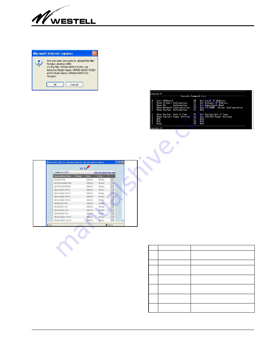
The confirmation window appears with the entered informa
tion. Click the OK button to initiate the upload process.
When the process is finished, click the Close button to close the
message window.
6.3.2
Deleting an Antenna Model
This section describes how to delete an antenna model from the
AISG‐RM3 controller.
Click the View button (in the
Antenna Config File
menu shown
in Figure 44) to display the entire list of antenna models stored
in the AISG‐RM3. Click on the vendor code (see the red arrow
in Figure 45) to go to the listing belonging to that vendor.
Figure 45. Entire List of Antenna Models
To delete an antenna model, find the antenna model name in the
list and click the Del button (in the same row) corresponding to
that model.
7.
USING THE CONSOLE INTERFACE
The purpose of the console access using a direct connection is to
provide a means to change system settings in the event that the
AISG‐RM3 controller cannot be otherwise accessed (for ex
ample, forgetting the IP address of AISG‐RM3).
7.1
How to Set Up Console Access
To set up a direct connection, connect a serial cable from a PC’s
COM port to the RS232C port of the AISG‐RM3 controller.
Use a terminal software program, such as the Hyperterminal
program provided in MS Windows, to connect with the
AISG‐RM3 controller. Set the terminal connection settings to:
Baud Rate = 9600
Stop bits = 1
Data bits = 8
No Parity
7.2
Using Console Commands
Once connection with the AISG‐RM3 controller is established,
the following is displayed:
Figure 46. Console Command List
Commands are numbered from 0 to 19, and some commands are
reserved for future use.
To execute a command that changes data, follow the steps below.
1.
Enter the number corresponding to a command first.
2.
If a data value is expected for a command, then enter the
data value associated with that command. Leave it blank to
keep the original value.
3.
Reboot the system when making changes to settings, such
as the IP, to apply the changes.
To display information on a command, enter the corresponding
number.
7.3
Viewing System Information
The following table shows commands that are used to display in
formation.
No.
Command
Description
1
Show Product Informa
tion
Displays the product model and serial number
of the AISG‐RM3 controller.
2
Show OS Information
Displays the OS version and memory, etc.
3
Show Network Config
uration
Displays the IP address of the AISG‐RM3 con
troller, the Gateway IP, and Subnet mask.
4
Show System Informa
tion
Displays the hardware and software version of
the AISG‐RM3 controller.
5
Show System Date &
Time
Displays the current system UTC date and
time.
6
Show Current Power
Setting
Displays the on/off status of AISG 12V and 24V
DC.
9
Help
For an explanation on how to use a command
to make changes.
Table 15. Command Display Numbers


