Section AIS‐RM3‐20B
030‐101806 Rev. A
R
1310IBRA
11
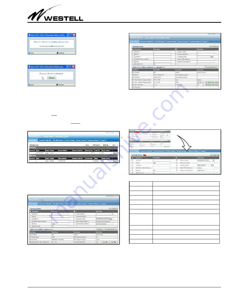
Close the message window.
5.2
Managing and Adjusting AISG Devices
Figure 28 displays a list of devices, in table row format. In the
“Detail” column (for each row of devices or Sector ID's in the
Device List) is a link to a panel to view the details for that partic
ular device. To view the detailed information on a specific device
(a TMA or RET), click on the Detail link of the device in the De
tail column.
Figure 28. Navigating to a Device Shown in Device List
RET Device Details.
Clicking on the Detail link for a RET device
opens a page (Figure 29) that shows device‐specific detailed in
formation retrieved from the selected RET device (bottom
half of screen), as well as its antenna data (top half of screen).
Figure 29. Sample RET (and Antenna) Details
TMA Device Details.
Clicking on the Detail link for a TMA
device opens a page (Figure 30) that shows device‐specific de
tailed information retrieved from the selected TMA device
(bottom half of screen), as well as its antenna data (top half of
screen).
Figure 30. Sample TMA Device (and Antenna) Details
5.2.1
Antenna Data
The “Antenna Data” section at the top half of a selected device
screen (Figure 31) shows detailed information about the an
tenna connected to the selected AISG device. Table 10 explains
the fields and options in the Antenna Data section or panel.
Figure 31. Top‐Half Antenna Data Area of a Device Screen
}
Field Name
Description / Constraint / Options
Sector ID
The sector ID.
Site ID
Base station site ID.
Installer ID
Installer's ID
Installation Date
Date in mmddyy format
Bearing
Antenna bearing in the range of 0359 degrees
Mechanical tilt
Installed mechanical tilt in degrees
Antenna Model
Select the antenna model from the dropdown list. If a
model is not in the list, refer to the section on “Antenna
Configuration File” on how to add a new antenna model.
Antenna Serial No.
Antenna serial number
Frequency Band
Frequency band(s) used by the antenna.
Beam Width
Beamwidth for each band in frequency order (separated by /)
Antenna Gain
Gain for each band in frequency order (separated by /)
Table 10. Antenna Data Section Fields
Make entries or changes per company practice, selecting the
items to save to the device. For example, in Figure 32 below, the
items within the red circle are selected. Only these values will be
saved to the device. Click on the Save Selected button to store
those data value(s) in the fields with their check‐boxes selected.
A message box indicates the save command is running.


