background image

Section AIS‐RM3‐20B

030‐101806 Rev. A

R

1310IBRA

14

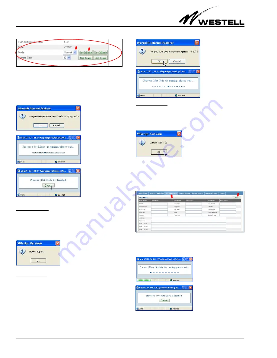
Figure 39. Setting the TMA Mode

The following confirmation window below appear. Click on the
OK button to initiate the process of changing the TMA mode.
After the process is done, close the subsequent message window.

5.2.3.2

Get Mode

Click on the Get Mode button in the bottom‐right corner of the
selected device panel (shown in Figure 36 and Figure 39) to get
the current TMA mode. The current TMA mode is displayed in
a pop up window, as shown below.

5.2.3.3

Set Gain

Select a TMA gain value in the range Min Gain – Max Gain in
the Current Gain drop‐down menu, then click on the Set Gain
button (shown in Figure 39). The confirmation window below is
displayed. Click on the OK button to initiate the process of chan­
ging the TMA gain. After the process is done, close the message
window.

5.2.3.4

Get Gain

Click on the Get Gain button in the bottom‐right corner of the
selected device screen (shown in Figure 36 and Figure 39) to ob­
tain the current TMA gain value. The current TMA gain value
is displayed in a pop up window, as shown below.

5.3

Site Information

The 

Site Information

 menu allows a user to record site informa­

tion. Click on the third tab at the top of the main menu to access
the 

Site Data

 panel (see Figure 40). After filling in the site data,

click the Save button to store the information in the AISG‐RM3.

Figure 40. Adding/Updating Site Information

The following process running window is displayed. Click on the
Close button after the process is done, to close the subsequent
message window.

Содержание AISG-RM3

Страница 1: ...son will be stated here This document reflects the Issue B equipment which accepts an input power supply range of 48VDC to 24VDC and uses con tact relays as alarm outputs Figure 1 AISG RM3 AISG Contro...

Страница 2: ...a reset button and three LEDs as shown in Table 1 and Table 4 below and ex plained in the paragraphs that follow LED Color State Status Description ALM alarm Red Steady AISG RM3 cannot ping default g...

Страница 3: ...C Normally Closed relay output Contact Capacity AC 125V 0 5A DC 24V 1A N O Normally Open relay output COMM Common N A GND Ground of I O channels Ground Table 3 Alarm Connector Pin outs 2 2 5 Ethernet...

Страница 4: ...ent Any in structions or information contained herein is subordinate to local codes operating procedures or practices CAUTION Improper grounding could be service affecting and cause service interrupti...

Страница 5: ...f the controller has been preset to 192 168 0 30 Enter this IP address for first time access It can be changed later The browser should display the Login page as shown in Figure 7 Figure 7 Login Scree...

Страница 6: ...enna Config File _ Summary Report _ Site Information _ Logout _ System Setting 4 1 Configure the System Settings Click on the System Setting tab as shown in Figure 11 to open the System Setting menu T...

Страница 7: ...age and power supply mode provided to the connected AISG devices can be changed Change the settings per company practice refer ring to Table 6 as needed then click on the Set button to apply the chang...

Страница 8: ...before triggering the alarm output This helps to remove any spurious non real alarm conditions 4 2 Manage User Accounts Click on the System Account tab on the main menu to open the user list accounts...

Страница 9: ...ized device is listed in the RET or TMA device list section panel according to its device type Devices are sorted by Sector ID in ascending order Scanning retrieves information previously stored in ea...

Страница 10: ...you are adding The Vendor Code is optional Click on the Add button to initiate the process If the process is successful the Device List will be updated Save the device information before moving on 5...

Страница 11: ...lf of a selected device screen Figure 31 shows detailed information about the an tenna connected to the selected AISG device Table 10 explains the fields and options in the Antenna Data section or pan...

Страница 12: ...lowed electrical down tilt range of the selected an tenna model Current Tilt Current electrical tilt Tilt value must be in the Min Tilt Max Tilt range If the tilt value cannot be retrieved the data va...

Страница 13: ...ISG version supported by the TMA device Figure 38 Viewing a Specific TMA Shown in Device List The fields in the selected TMA Device panel are listed in Table 12 Field Name Description Constraint Optio...

Страница 14: ...ation window below is displayed Click on the OK button to initiate the process of chan ging the TMA gain After the process is done close the message window 5 2 3 4 Get Gain Click on the Get Gain butto...

Страница 15: ...TMA Gain SET_MODE Sector ID mode Set TMA Mode Note The key word in the Action column is used in the log to represent the recorded action Information re lated to an action in the Information Recorded c...

Страница 16: ...n one vendor code the vendor code is also shown after the vendor name Select the vendor name with the right vendor code to upload the configuration file The vendor code must match the vendor code on t...

Страница 17: ...the AISG RM3 controller Set the terminal connection settings to Baud Rate 9600 Stop bits 1 Data bits 8 No Parity 7 2 Using Console Commands Once connection with the AISG RM3 controller is established...

Страница 18: ...ke effect 15 Set System Date Time Changes the system UTC date and time 16 Set 12v 24v Power Setting Switches 12V 24V DC on or off The default is N which represents off Table 16 Command Display Numbers...

Страница 19: ...rmware Once finished perform a manual reboot of the controller 3 Refresh the browser to reload the user interface you will find the changed upgraded firmware 9 ERROR ALARM CODES MESSAGES The following...

Страница 20: ...n between the AISG RM3 system and the device 0x53 No Responding X Lost connection between the AISG RM3 system and the device 0x54 Function Fail Unexpected result from the AISG RM3 system 0x59 Timeout...

Страница 21: ...ling programs and local codes and per state statutes 12 SPECIFICATIONS 12 1 Electrical Specifications A Power supply input DC 24V max 3 2A or 48V max 1 6A B Power supply to AISG devices 24V max 2 0 A...

Страница 22: ...Amplifier LTE Long Term Evolution mA milliAmps MHz Megahertz PDU Power Distribution Unit RES Receiver Enhancement System RF Radio Frequency Rx Receive TMA Tower Mounted Amplifier Tx Transmit V Volts...

Отзывы: