Pro-EC44 2-Loop Graphical Profile Controller & Recorder
Pro-EC44 Product Manual - 59540-2 September 2014
Page 104
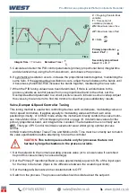
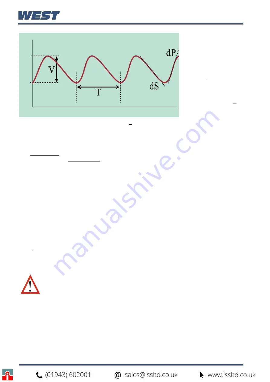
V
= On-going Peak-to-Peak
variation
T
= Time period of
oscillation (minutes)
d
S
= Maximum rate of rise
d
P
= Maximum rate of fall
R
= Ratio
Primary proportional
band
=
Pb.P
=
Secondary proportional
band
= R x Pb.P
5. Calculate and enter the PID control parameters (primary proportional band, integral time
and derivative time) using the formulas shown, and observe the process.
6. If symmetrical oscillation occurs, increase the proportional bands together, maintaining the
same ratio. If the asymmetrical oscillation occurs, adjust the ratio between the bands until
it becomes symmetrical, then increase the bands together, maintaining the new ratio.
7. When the PID tuning values have been determined, if there is a disturbance to the
process variable as control passes from one proportional band to the other, set the
Overlap/Deadband parameter to a small positive value to introduce some overlap. Adjust
this value by trial and error to find the minimum value that gives satisfactory results.
Valve, Damper & Speed Controller Tuning
This tuning method is used when controlling devices such as dampers, modulating valves or
motor speed controllers. It applies equally to modulating valves with their own valve
positioning circuitry, or in VMD mode where the instrument directly controls the valve motor
–
see Valve Motor Drive / 3-Point Stepping Control on page 14
. It determines values for the
primary proportional band, and integral time constant. The derivative time is normally set to
OFF.
This type of PI Control
minimises valve/motor wear whilst giving optimal process
control.
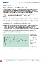
In VMD modem the Motor Travel Time and Minimum On Time must be correctly set to match
the valve specifications before attempting to tune the controller.
CAUTION:
This technique is suitable only for processes that are not
harmed by large fluctuations in the process variable.
1. Set the setpoint to the normal operating process value (or to a lower value if overshoot
beyond this value is likely to cause damage).
2. Set the Primary Proportional Band a value approximately equal to 0.5% of the input span
for the loop to be tuned. (
Span is the difference between the scaled input limits
).
3. Set the Integral & Derivative time constants both to OFF.
4. Switch on the process. The process variable should oscillate about the setpoint.
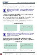
Derivative Time
=
Integral Time
= T minutes
P
ro
c
es
s
V
a
riabl
e
Time
Содержание Pro-EC44
Страница 1: ...Pro EC44 2 Loop Graphical Profile Controller Recorder Pro EC44 User Guide 59540 2 ...
Страница 2: ......
Страница 6: ......

