Pro-EC44 2-Loop Graphical Profile Controller & Recorder
Pro-EC44 Product Manual - 59540-2 September 2014
Page 240
Extending Functionality via Software
LED Functions & Labels
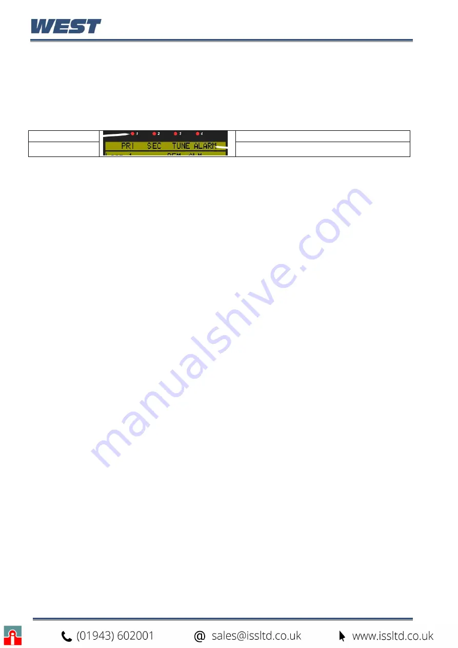
The allocated functions and descriptive labels for the 4 LED indicators can be changed with
the PC software, replacing the default PRI; SEC; TUNE; ALARM functions. These
parameters can be found in the LED settings section of the software’s Display Configuration
functional group.
LED 1 to 4
LED LABELS (
max 5 characters
)
Possible functions for each of the LEDs are: Loop 1 or 2 primary/secondary/valve control
output indication (output ON = LED ON), or driving them from a logical OR combination of the
alarm/profile event/digital inputs/auto-tune status/manual mode. This logical combination can
be inverted to create a logical NOR function for the LEDs.
The user can create new 5 characters LED labels for the main and alternate language.
Alarm Status Screen Labels
The titles “Alarm
n
” used in the alarm status screen can be replaced with the software. Two
separate sets of 8 characters labels can be entered for each of the seven alarms. One label
set is used when the main display language has been selected, the other is used when the
alternate language is in use.
Configuring the Supervisor Mode
The purpose of the supervisor mode is to allow selected operators access to a
“lock-code”
protected sub-set of the configuration parameters, without giving them the higher level
configuration menu unlock code Up to 50 configuration parameters can be selected for
inclusion in the supervisor mode screen sequence. If the parameter is normally displayed on
screen with another parameter, both parameters will appear.
It is not possible to configure supervisor mode screens without using the software.
To define these screens, first select Supervisor Mode from the mode drop-down list, then
select the functional group containing the parameter to be added. Highlight the parameter
name and click the Add Entry button. The Move Entry Up and Down buttons are used to
change the order which the parameters will appear in
the instruments’ Supervisor Mode.
Unwanted entries can be highlighted and deleted with the Remove Entry button.
Configuring Custom Display Screens for the Extended Operator Mode
Users can access a sub-set of the configuration parameters at the end of the normal
operation mode if this additional screen sequence is defined from the software. Up to 50
parameters from configuration menus can be selected for inclusion in the screen sequence.
If the parameter is normally displayed on screen with another parameter, both parameters
will appear.
It is not possible to configure custom display screens without using the software. To define
these screens, first select Extended Operator Mode from the mode drop-down list, then
select the functional group containing the parameter to be added.
Highlight the parameter name and click the Add Entry button. The Move Entry Up and Down
buttons are used to change the order which the parameters will appear at the end of the
normal operator screens.
Unwanted entries can be highlighted and deleted with the Remove Entry button.
Содержание Pro-EC44
Страница 1: ...Pro EC44 2 Loop Graphical Profile Controller Recorder Pro EC44 User Guide 59540 2 ...
Страница 2: ......
Страница 6: ......

