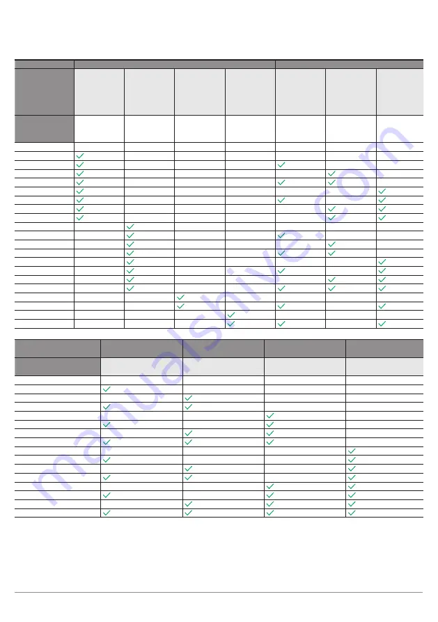
background image

Operation

138

Display 3

Muting mode function

Muting options

Muting mode 
function

Cross 
muting

2-sensor  
linear muting

4-sensor 
linear 
muting with 
sequence 
monitoring

4-sensor 
linear muting 
with time 
monitoring

Maximum 
long muting 
duration  
(8 hours)

Muting  
enable 
function

Belt stop 
function

As displayed in 
the menu tree 
under MUTG

X

2L

LSEQ

LTME

TIME

ENAB

STOP

A

×

×

×

×

×

×

×

B

×

×

×

×

×

×

C

×

×

×

×

×

D

×

×

×

×

×

E

×

×

×

×

F

×

×

×

×

×

G

×

×

×

×

H

×

×

×

×

J

×

×

×

×

K

×

×

×

×

×

×

L

×

×

×

×

×

N

×

×

×

×

×

P

×

×

×

×

R

×

×

×

×

×

S

×

×

×

×

T

×

×

×

×

U

×

×

×

V

×

×

×

×

×

×

X

×

×

×

×

Y

×

×

×

×

×

×

Z

×

×

×

×

Display 4 – Further 
muting options

Partial muting

Gap suppression

Muting end through 
clearing of the ESPE

Override function

As displayed in the 
menu tree under MUTG

PART

GAPS

END

OVRR

A

×

×

×


×

B

×

×

 ×

C

×

×


×

D

×


×

E

×

×


×

F

×


×

G

×


×

H


×

J

×

×

×

K

×

×

L

×

×

N

×

P

×

×

R

×

S

×

T

Содержание SEFB Series

Страница 1: ...m Safety Light Array Operating Instructions Translation of the Original Operating Instruction Subject to technical changes Available as PDF file only Revision level 06 09 2021 Doc No 1038510 Version 1...

Страница 2: ...ant Safety Precautions for Machine Operators 12 2 6 General Safety Precautions 12 2 7 Approvals and IP Protection 13 3 Product Description 13 4 Technical Data 15 4 1 General Technical Data 15 4 2 Resp...

Страница 3: ...ce to Reflective Surfaces 42 5 2 Functions 44 5 2 1 Functions Overview 44 5 2 2 Combinable Functions 45 5 2 3 Operational Functions 46 5 2 3 1 Safety Operating Mode Automatic Restart 46 5 2 3 2 Start...

Страница 4: ...Settings 76 5 2 5 3 Signal Output 76 5 2 5 4 Integrated Indicator Lamp 77 5 2 5 5 Signal Strength Display 77 5 2 5 6 Memory Function 78 5 2 5 6 1 Access to the Memory Card 79 5 2 5 6 2 Suitable Memor...

Страница 5: ...art Inhibit RES 101 9 5 3 Parametrization of the Contactor Monitoring EDM 101 9 5 4 Parametrization of the Beam Coding CODE 102 9 5 5 Parametrization Cascading CASC 103 9 5 6 Parametrization Muting MU...

Страница 6: ...tor on the Receiver SEFB 142 13 2 3 Error Indicator on the Receiver SEFB Muting 142 13 3 Diagnosis Codes on the Receiver SEFB Muting 143 13 3 1 Codes for Information and Warnings 143 13 3 2 Codes for...

Страница 7: ...Multi Beam Safety Light Array 7 16 3 Order Notes 158 16 4 EU Declaration of Conformity 158 16 5 Index of Changes 158 16 6 Index of Abbreviations 159 16 7 Index of Figures 161...

Страница 8: ...fore using the product and must be kept on hand for later reference 1 2 Target Group These operating instructions are aimed at developers planners installers owners and machine operators who want to s...

Страница 9: ...s Subject to change without notice A valid declaration of conformity can be found at www wenglor com in the product s separate download area wenglor excludes all liability in the event of Non complian...

Страница 10: ...at all times Additional mechanical safety equipment is installed so that the safety field must be passed through to access hazardous machine parts Care is taken during installation to ensure that the...

Страница 11: ...hazardous situations Observe instructions regarding use for intended purpose 2 3 Personnel Qualifications Suitable technical training is a prerequisite In house electronics training is essential Train...

Страница 12: ...rved body parts and people to be protected may not be detected If changes are made to the electrical integration in the machine control or the mechanical installation of the safety light array a new r...

Страница 13: ...r When an object penetrates the safety field and one or multiple beams are interrupted a switch command is triggered on both safety outputs Together with the downstream evaluation this prevents a haza...

Страница 14: ...th sequence time monitoring Different adjustable muting functions Restart inhibit and safety operating mode automatic restart Contactor monitoring monitoring of external switching elements Cascading w...

Страница 15: ...24 300 mm Range 0 5 m 50 m Aperture angle 2 5 Wavelength emitter typ 630 nm Coated optics Yes Ambient light immunity for continuous light 10 000 Lux Electrical data Response time See section 4 2 page...

Страница 16: ...High 11 V 6 30 mA Mechanical data Housing material Aluminum Degree of protection IP65 IP67 Connection type emitter M12 plug 5 pin Connection type receiver M12 plug 8 pin system connection M12 socket 8...

Страница 17: ...unting options in order to assure compliant error free operation Connection type Tightening torque Nm M12 0 4 4 2 Response Times SEFB muting SEFB Beam distance mm Number of beams Response time ms SEFB...

Страница 18: ...Technical Data 18 4 4 Housing Dimensions Safety Light Array 4 4 1 SEFB Muting Drawing 1 SEFB412 2 beams 500 mm Drawing 2 SEFB413 3 beams 400 mm 1 Emitter 2 Receiver...

Страница 19: ...Multi Beam Safety Light Array 19 Drawing 3 SEFB414 4 beams 300 mm Overall housing dimensions 1 Emitter 2 Receiver 4 4 2 SEFB Drawing 4 SEFB422 2 beams 500 mm 1 Emitter 2 Receiver...

Страница 20: ...Technical Data 20 Drawing 5 SEFB423 3 beams 400 mm Drawing 6 SEFB424 4 beams 300 mm 1 Emitter 2 Receiver...

Страница 21: ...EFX001 For attachment to the ends top bottom of the ESPE Scope of delivery 1 piece Including screws and washers Mounting bracket ZEFX002 For attachment to the ends top bottom of the ESPE Installation...

Страница 22: ...the profile at the side of the ESPE Installation in protection column Z2SSxxx Scope of delivery 2 pieces Including screws washers and slot nut Mounting bracket ZEMX001 For wall profile mounting Scope...

Страница 23: ...or 1 Power Supply voltage Green GN 2 CODE Beam coding Yellow YE 3 HI RAN High Range Yellow YE 4 ERROR Error Red RD Input elements Apply Menu down 4 6 2 Control Panel Receiver SEFB Muting LEDs Display...

Страница 24: ...RROR Error Red RD 5 RES confirmation requirement Yellow YE 6 EDM Contactor monitoring Yellow YE 7 CODE Beam coding Yellow YE 4 7 Scope of Delivery The SEFB4xx set consists of the following components...

Страница 25: ...2SM002 Z2SM003 930 mm 1380 mm 1830 mm Floor mounting ZMBSZ0001 Wall mounting ZMBSZ0002 Mounting Technology ESPE at top bottom ZEFX001 ESPE at slot in side ZEMX001 ESPE at top bottom in protection colu...

Страница 26: ...on ends top bottom of the ESPE Installation in safety column Z2SSxxx ZEFX003 Stainless steel Mounting on the side profile of the ESPE Installation in safety column Z2SSxxx ZEMX001 Stainless steel Moun...

Страница 27: ...ht plug S06 S06 35 Emitter 5 m ZAS35R501 10 m ZC4L001 M12 1 5 pin PVC Angle plug Straight plug S06 S06 35 Emitter 3 m S35W 3M 5 m S35W 5M S35G 5M 4 9 3 Connection Cables M12 1 8 pin PVC Straight plug...

Страница 28: ...several sides with just one ESPE NOTE The range of the ESPE is reduced by approximately 10 per utilized mirror Order number Mirror length Housing material Mounting Path folding mirror Z2UG001 80 mm A...

Страница 29: ...Multi Beam Safety Light Array 29 Application example 1 Emitter 2 Receiver 3 Safety column with path folding mirror Z2SU00x...

Страница 30: ...is possible depending on the mounting used Order number Installation space Housing material Material protective disc Safety column with protective disc Z2SS001 1252 mm Aluminum Polycarbonate Z2SS002...

Страница 31: ...ng the T plug to the receiver and connecting an IO Link master EFBL003 enables the IO Link connection of the device to be used This guarantees the IO Link signal extraction and enables the wTeach2 sof...

Страница 32: ...menting standard muting solutions The retro reflex sensors P1KL020 are used as muting sensors together with the reflector RE6040BA Connection equipment and mounting technology in the required quantiti...

Страница 33: ...Multi Beam Safety Light Array 33 Z2MG003 Further information can be found in the operating instructions for the muting sets...

Страница 34: ...r muting and cascading are possible at the same time Two sensor muting Four sensor muting Belt stop Muting enable Full Muting Enable Port 5 Port 3 Port 1 Port 6 Port 4 Port 2 Port Connection Use 1 M12...

Страница 35: ...1 Laser Alignment Tool Z98G001 Further information can be found in the operating instructions for the Z98G001 4 9 12 LED Light Strips Z99G001 Further information can be found in the operating instruct...

Страница 36: ...ject Engineering This chapter contains important information for correct integration of the ESPE in the machine 5 1 Engineering 5 1 1 Safety Field Beam distance Sfb range emitter receiver safety field...

Страница 37: ...Using path folding mirrors reduces the range 5 1 2 Securing the Danger Zone The danger zone must be secured by means of the ESPE alone or by means of the ESPE in combination with additional mechanica...

Страница 38: ...nce The general formula for calculating the safety clearance S is S K T C or S K t1 t2 t3 C S mm Safety clearance measured from the danger zone to the safety field K mm s Approach speed C Additional c...

Страница 39: ...ch speed with vertical safety field K 2000 mm s K 1600 mm s if SRO 500 mm T s Total response time T t1 t2 t3 t1 s Response time of the ESPE t2 s Response time of the safety switching device t3 s Machi...

Страница 40: ...of the top edge of the safety field 900 1000 1100 1200 In accordance with EN ISO 13855 the following minimum and maximum heights must be observed Number of beams Beam distance in mm Height above refer...

Страница 41: ...between row and column you will find the value for CRO In this row go to the left column Here you will find the value for a DANGER Risk of personal injury or property damage in case of non compliance...

Страница 42: ...100 mm S 1 628 mm 5 1 4 Minimum Clearance to Reflective Surfaces DANGER Risk of personal injury or property damage with reflective surfaces within the aperture angle between the emitter and receiver T...

Страница 43: ...ay 43 Distance between the emitter and receiver m Minimum clearance m mm 6 6IE P P PP m mm minimum clearance mm Sfb m clearance from emitter to receiver m 0 25 3 0 131 4 175 5 218 10 437 15 655 20 873...

Страница 44: ...ar muting sequence monitoring Section 5 2 4 5 X Four sensor linear muting time monitoring Section 5 2 4 6 X Adjustable muting duration Section 5 2 4 7 2 X Belt stop signal Section 5 2 4 7 3 X Muting e...

Страница 45: ...tactor monitoring Beam coding Cascading Muting complete Partial muting Full resolution Safety operating mode automatic restart Start up disabling and restart inhibit Contactor monitoring Beam coding C...

Страница 46: ...mode prevents the machine from restarting automatically by ensuring that the OSSDs remain in off state This status is retained even when the supply voltage is switched on again e g after a power fail...

Страница 47: ...he contacts to be detected The contactor monitoring RES is parametrized on the receiver If the connected contactors do not switch in the expected time the ESPE switches to safe state OSSD OFF ERROR Th...

Страница 48: ...FF The setting for matched emitters and receivers must be identical both coding ON or both coding OFF 5 2 3 5 Range The range is the mechanically usable distance between the emitter and receiver In or...

Страница 49: ...n the receiver The terms Master or Slave are used to differentiate between the components Master component with direct connection to the machine control Slave components with connection to the master...

Страница 50: ...separately to the supply voltage connection cable M12 4 5 pin For details on the electrical connection see 16 2 3 Connection Examples Cascading on page 156 5 2 3 6 2 Cascading via Muting Connection Bo...

Страница 51: ...not permitted If these sensors are used incorrect signals may impair the safety function 5 2 3 6 4 Cascading of Contact based Safety Components WARNING Contact based safety circuits e g emergency sto...

Страница 52: ...nsors are arranged so that their beams cross Additional signals for example from muting sensors or a PLC are required to activate the muting function This means that the ESPE can check that the muting...

Страница 53: ...l 0 OSSDs on Muting inactive DANGER The muting must be triggered by at least two independent signals The use of software controlled signals e g PLC is permitted if at least one signal comes from anoth...

Страница 54: ...multiple inputs Each signal must only be assigned to one input The user must take suitable measures see EN ISO 13849 2 Tab D 4 to prevent cross connection between muting signals DANGER When mounting t...

Страница 55: ...t their beams cross The point of intersection is within the danger zone The distances a and b represent the distances between the muting object and a separating safeguard fence They must be designed s...

Страница 56: ...s than 200 mm and must be within the danger zone It must be kept as small as possible To prevent manipulation with the feet the intersection point of the MS must be at the height of the lowest beam of...

Страница 57: ...the maxi mum muting duration is reached Signal path Muting active SF penetration Figure 4 Signal path during cross muting NOTE The safety can be increased further by positioning the MS at different he...

Страница 58: ...can enter the danger zone unnoticed while the muting object is passing through the ESPE A sample arrangement of the sensors is shown in the following figure Danger zone Figure 5 Arrangement two senso...

Страница 59: ...t MS1 is activated first followed by MS2 Both sensors must be activated within a time frame of 4 seconds 2 Muting active MS1 and MS2 active Penetration of the safety field muting object passes through...

Страница 60: ...hed The direction setting function can be used to restrict the permissible direction of the object transport to one direction The four sensor linear muting with sequence monitoring does not use time m...

Страница 61: ...Distances NOTE The muting object must be at least long enough that all 4 MS are triggered at the same time during the muting sequence This parameter is indicated by the value d5 ATTENTION The distanc...

Страница 62: ...ting remains active 4 Muting active MS1 MS2 penetration of the safety field MS3 and MS4 active 5 Muting active MS2 penetration of the safety field MS3 and MS4 active MS1 has become inactive 6 Muting a...

Страница 63: ...ime required Depending on which MS is activated first the following MS must also be activated within 4 s Transport into the danger zone MS1 MS2 transport out of the danger zone MS4 MS3 The direction s...

Страница 64: ...to the distance from the first MS to the last MS This parameter is indicated by the value d5 ATTENTION The distance d5 must be at least 500 mm To reduce the risk of unintentional triggering of the mu...

Страница 65: ...pted the OSSDs remain in the ON state 3 Muting active MS1 MS2 penetration of the safety field MS3 active Muting remains active 4 Muting active MS1 MS2 penetration of the safety field MS3 MS4 are activ...

Страница 66: ...dditional function may be used 0 Additional function may be used but not at the same time as the other marked functions Additional function may not be used Function is activated automatically by the o...

Страница 67: ...uting sequence is continued Sample signal sequence using cross muting as an example Muting active Belt stop signal Safety during belt stop To make it more difficult to bypass the ESPE with the belt st...

Страница 68: ...omment 1 Muting enable is activated Function is activated in the parametrization Basic requirement for using the function 2 Muting inactive Muting Enable input is activated by an external signal 3 Mut...

Страница 69: ...mpletely before a muting cycle can be started in the opposite direction If a change in direction takes place while a muting cycle is in progress this is likely to violate a time or sequence condition...

Страница 70: ...rea 2 Area is muting relevant Here the beams of the ESPE are bridged depending on the muting sequence Figure 14 Partial muting NOTE Area 2 muting area can be taught in by transporting the object into...

Страница 71: ...ting_Enable must be active until both muting signals are applied and muting is activated 4 MS1 and MS2 become active within 30 seconds and muting is therefore active The following figure shows the sig...

Страница 72: ...this case the object stops and prevents a valid muting sequence from being carried out The Override function enables the object to be transported out of the muting area despite the safety field being...

Страница 73: ...de DANGER There must be no persons in the danger zone during override The entire danger zone must be clearly visible by the operator during the override NOTE While the override is active the illuminat...

Страница 74: ...ked Shows the position of the first blocked beam as viewed from the control panel If the safety field is free FBB 0 Last blocked beam Abb LBB Last Beam Blocked Shows the position of the last blocked b...

Страница 75: ...CBB Numbers of Cumulated Beams Blocked 2 1 beam NOBJ Numbers of Objects 1 2 Figure 17 Values of the measuring function NOTE The measuring function is dependent on the parametrized operating modes and...

Страница 76: ...put can be used as a digital PNP output signal output The following functions can be assigned to the signal output ATTENTION On the receiver of the ESPE Pin 6 IO Link output is not suitable for safety...

Страница 77: ...isplays within the system The muting status display can not be deactivated Transparent end cap with integrated indicator lamp Setting options Status ESPE Display indicator lamp Muting status Active Wh...

Страница 78: ...ation for the ESPE is saved on the PC file system Parameter configura tion of an ESPE takes place via the control panel and is saved on the card Parameter configura tion of an ESPE takes place via the...

Страница 79: ...memory capacity max 8 GB File system type FAT32 The microSD card can be removed replaced at any time without impairing operation Preferred type wenglor order no ZNNG013 5 2 5 6 3 File System The foll...

Страница 80: ...d unintentional changes to the ESPE The parameters of the ESPE may only be configured by authorized personnel The authorized personnel are also responsible for maintaining the safety function The rece...

Страница 81: ...er always as a signal output see 5 2 5 3 Signal Output on page 76 With the emitter as a digital input without function ATTENTION The IO Link interface is not safety related This means that both OSSDs...

Страница 82: ...he device making reference to damage in transit 6 2 Storage The following points must be taken into consideration with regard to storage Do not store the product outdoors Store the product in a dry du...

Страница 83: ...be possible to reach over reach under reach around or move the ESPE The arrangement of the emitter and receiver must ensure that persons or body parts are reliably detected if they enter the danger z...

Страница 84: ...be mounted parallel to each other and at the same mounting height Parallel alignment The emitter and receiver must be mounted so that a rectangular safety field is formed Same alignment in relation t...

Страница 85: ...om the corresponding emitter This can be guaranteed with the following measures Anti parallel arrangement see Fig Shielding e g with dividing walls see Fig Minimum distance at the side 2 m see 5 1 4 M...

Страница 86: ...s mounted in a mechanically secure fashion Specified torque values must be complied with see 4 1 General Technical Data on page 15 Use suitable mounting technology in order to ensure correct installat...

Страница 87: ...ulti Beam Safety Light Array 87 7 2 2 Installation with Mounting Bracket ZEFX002 Figure 20 Installation with ZEFX002 7 2 3 Installation with Mounting Bracket ZEFX003 Figure 21 Installation with ZEFX00...

Страница 88: ...tallation situation To remove the warning strip or to mount it on the opposite side proceed as follows Position a small screwdriver at the end of the warning strip and lever it carefully out of the gr...

Страница 89: ...re to comply poses risk of fatal injury Disconnect the machine from the power supply while carrying out the electrical installation The machine could start up unintentionally while you are connecting...

Страница 90: ...onnection only with SEFB muting Receiver E1 MS3 belt stop Full Muting Enable E2 MS4 Muting Enable E3 MS1 E4 MS2 RES Override NOTE Pin 1 and Pin 3 on the extension connection are only intended for supp...

Страница 91: ...t Analog Output Ground for the Analog Output Block Discharge Valve Output Valve Control Output Valve Control Output 0 V Synchronization Ground for the Synchronization Receiver Line Emitter Line Ground...

Страница 92: ...dictory settings NOTE Changes to the configuration may only be made by authorized personnel The required password must be managed with suitable security 9 2 Preparation of the Parametrization Before c...

Страница 93: ...of the configuration menu is divided into the following steps 1 Press and hold the Menu down key until the red ERROR LED goes out approx 2 s 2 Release the key and wait until the red ERROR LED lights...

Страница 94: ...ng parameter configuration Meaning Display during operation HI RANGE Flashing duty cycle 15 LED on LED off Low Range HI RAN Flashing duty cycle 85 LED on LED off High Range HI RAN CODE Flashing duty c...

Страница 95: ...ettings are active If parameters configuration is started from an error state all settings are reset see section 9 4 1 page 95 9 4 1 Default Settings Function Default settings Restart inhibit Off Cont...

Страница 96: ...uration 96 ERROR SIG LOW RES EDM CODE OSSD Figure 26 Timing diagram receiver for calling up the menu 9 4 3 Menu Structure The menu is laid out as follows Restart inhibit HI RANGE CODE Encoding EDM Con...

Страница 97: ...5 LED on LED off Restart inhibit ON RES EDM Flashing duty cycle 15 LED on LED off Contactor monitoring OFF EDM Flashing duty cycle 85 LED on LED off Contactor monitoring ON EDM CODE Flashing duty cycl...

Страница 98: ...e section 9 4 12 page 151 must be used to write them to the device memory via RUN SAVE Otherwise the changes will be lost when the device is restarted 9 5 1 Default Settings Function Default settings...

Страница 99: ...sensor linear muting STOP Belt stop 8H 8 hours CODE Beam coding LSEQ four sensor linear muting sequence monitoring ENAB Muting enable A Direction setting A CASC Cascading LTME four sensor linear mut i...

Страница 100: ...SIGN Signal output MUT Muting active LAMP Indicator lamp CONT Weak signal contamination ADJ Signal strength display SYNC Synchronization run RSET Reset to default settings RDY Ready state CARD Access...

Страница 101: ...1 Acknowledge the RES mode by pressing the key 2 Choose from ON OFF and using the or key The parameters to be selected are shown flashing 3 Acknowledge the selection by pressing the key 4 A selected...

Страница 102: ...operating modes and partial muting beam coding must first be taught in Blanking or muting objects can then be taught in during an additional parameters configuration procedure The following steps are...

Страница 103: ...R Switch off OSSD RES SIG LOW ERROR Back OSSD RES SIG LOW ERROR Level 0 Level 1 1 Acknowledge the CASC mode by pressing the key 2 Choose from ON OFF and using the or key The parameters to be selected...

Страница 104: ...four sensor linear muting time moni toring OSSD RES SIG LOW ERROR Back OSSD RES SIG LOW ERROR Level 0 Level 1 1 Acknowledge the MUTG mode by pressing the key 2 Choose from OFF X 2L LSEQ LTME and using...

Страница 105: ...ting sequence There are two values to choose from 300S Muting duration max 300 s 8H Muting duration max 8h For more information on the muting duration function see section 5 2 4 7 2 page 66 OSSD RES S...

Страница 106: ...ed once the valid sequence MS or set time is complete For more information on the Muting end through clearing of the ESPE function see section 5 2 4 7 6 page 69 OSSD RES SIG LOW ERROR Switch off OSSD...

Страница 107: ...ransport items with gaps brief interruptions in the muting signal are to be expected The gap suppression function pre vents this from ending the muting function ON The muting signals MS1 MS4 are delay...

Страница 108: ...ensor linear muting a Timeout muting duration OSSD RES SIG LOW ERROR 300 sec There is a time limit on the maximum duration of an active muting sequence There are two values to choose from 300S Muting...

Страница 109: ...urrently blocked e g T004 4 beams 1 beam is automatically added to the actual object size at the ends of the area to increase the availability through potential tolerances If no beam was blocked durin...

Страница 110: ...Back OSSD RES SIG LOW ERROR g Override OSSD RES SIG LOW ERROR Switch on The override function enables a stopped object to be removed from the muting area This can be necessary if a valid muting sequen...

Страница 111: ...two values to choose from 300S Muting duration max 300 s 8H Muting duration max 8 h For more information on the muting duration function see section 5 2 4 7 2 page 66 OSSD RES SIG LOW ERROR 8 hours O...

Страница 112: ...t of the desired size into the safety field The display T000 shows the number of beams currently blocked e g T004 4 beams 1 beam is automatically added to the actual object size at the ends of the are...

Страница 113: ...s interrupted due to a conveyor belt stop for example ON Override activated OFF Override deactivated For more information on the override function see section 5 2 4 7 10 page 72 OSSD RES SIG LOW ERROR...

Страница 114: ...SIG LOW ERROR Selection OSSD RES SIG LOW ERROR Energy saving mode OSSD RES SIG LOW ERROR Back OSSD RES SIG LOW ERROR Level 0 Level 1 1 Acknowledge the DISP mode by pressing the key 2 Choose from STD...

Страница 115: ...play OSSD RES SIG LOW ERROR Reset to default settings OSSD RES SIG LOW ERROR Memory card OSSD RES SIG LOW ERROR Password protection OSSD RES SIG LOW ERROR Back OSSD RES SIG LOW ERROR Level 0 Level 1 1...

Страница 116: ...FF Output deactivated RES Acknowledgment prompt OSSD OSSD switching states MUT Muting status CONT Contamination warning SYNC Synchronous run RDY Signals that the ESPE is ready for operation For more i...

Страница 117: ...OSSD RES SIG LOW ERROR Beam intensity I stands for signal strength intensity The setting can be canceled via After the ESPE is switched on the signal strength is displayed for 30 s as stan dard For m...

Страница 118: ...rning messages may appear when accessing the SD card see section 13 3 4 page 147 For more information on the memory card see section 5 2 5 6 page 78 OSSD RES SIG LOW ERROR Load OSSD RES SIG LOW ERROR...

Страница 119: ...Level 2 2 Save the loaded parameter configuration to the sensor memory Run Selection Save parameter configuration Selection OSSD RES SIG LOW ERROR OSSD RES SIG LOW ERROR Level 0 Level 1 3 ESPE carrie...

Страница 120: ...n was saved via the menu selection Run Save Otherwise the changes will be lost when the sensor is restarted To save the parameter configuration proceed as follows Run Selection Save parameter configur...

Страница 121: ...software IODD and the interface protocol are available on the wenglor homepage in the download area for the product If the connection is successful the following operating displays are shown during t...

Страница 122: ...Configuration 122 Segment display Digit 1 Digit 2 Digit 3 Digit 4 NOTE The parameter configuration on the control panel see section 9 3 page 92 section 9 4 page 95 always has priority over setting vi...

Страница 123: ...m FBB 0 no beam blocked 1 x beam number from the control panel 255 receiver not in synchronous run Time for status change between MS3 MS4 0 250 in 0 1 s A NBB B MutingTime HighByte Number of blocked b...

Страница 124: ...ettings Selection of the muting type and setting of the muting parameters Teach in settings Param TeachIn Start and end of the teach process relevant for Partial muting Paramt TeachIn Value Number of...

Страница 125: ...alled correctly with the correct electrical connection Cross muting with muting end through ESPE is to be parametrized 1 Password entry PasswordParamEntry 0000 current password write ESPE enters param...

Страница 126: ...art delete or update 2 Password entry PasswordParamEntry 0000 current password write ESPE enters parametrization mode see above for operating display Parameters can now be changed and saved 3 Carry ou...

Страница 127: ...has been completed successfully see section 8 page 89 The parameter configuration has been completed successfully see section 9 page 92 For operating modes and functions involving teach in processes t...

Страница 128: ...imal Signal strength is very good Synchronization complete OSSDs can be activated The optimal alignment for high process reliability has been achieved OSSD SIG LOW ERROR Weak Signal strength is weak S...

Страница 129: ...SD RES SIG LOW ERROR Medium Signal strength is adequate with a small reserve for changes e g contamination alignment Synchronization complete SYNC point OSSDs can be activated If possible improve the...

Страница 130: ...ried out to determine whether the ESPE has been chosen correctly accord ing to the local regulations and whether it offers the necessary protection when used as intended The effectiveness of the ESPE...

Страница 131: ...O Link Relevant information can be found in the interface protocol of the ESPE 11 1 1 Operating Displays Emitter The following status displays can be read off in normal operation SIG LOW POWER ERROR C...

Страница 132: ...the selected operating mode no beam has a weak signal With OSSDs OFF SIG LOW is also always OFF LED lit SIG LOW All beams are detected according to the selected operating mode but at least one beam ha...

Страница 133: ...SIG LOW LED off SIG LOW All beams are detected according to the selected operating mode no beam has a weak signal LED lit SIG LOW All beams are detected according to the selected operating mode but at...

Страница 134: ...as follows Input 3 Input 1 Input 4 Input 2 Muting active SYNC The following rules apply M in the first M indicates that a muting error is present The meaning of the error is indicated by a code in th...

Страница 135: ...on can be read off via the LED displays For more information on the operating displays see section 11 1 1 page 131 Receiver SEFB The current parameter configuration can be read off via the LED display...

Страница 136: ...SIG LOW ERROR Display 1 Display 2 Display 3 Display 4 Display 1 Operating functions Restart inhibit Contactor monitoring Cascading Beam coding As displayed in the menu tree RES EDM CASC CODE A B C D E...

Страница 137: ...resolution is reduced by Float blanking The tolerance between the minimum and maxi mum object size is As displayed in the menu tree under BLNK BLNK OFF FIX FIXT REDU FLB A B C D 1 beam E 2 beams F 3...

Страница 138: ...g Maximum long muting duration 8 hours Muting enable function Belt stop function As displayed in the menu tree under MUTG X 2L LSEQ LTME TIME ENAB STOP A B C D E F G H J K L N P R S T U V X Y Z Displa...

Страница 139: ...mination of any kind has a direct impact on the signal strength of the ESPE and may result in malfunctions The panes may only be cleaned with the supply voltage disconnected It is advisable to clean t...

Страница 140: ...148 NOTE The supplied sticker Instructions for regular inspection must be mounted in a clearly visible location close to the relevant ESPE Do not clean the ESPE with solvents or cleaning agents which...

Страница 141: ...e must be shut down if the error cannot be definitively explained or properly eliminated Required action as specified in case of fault 13 2 Error Indicators 13 2 1 Error Indicator on the Emitter Displ...

Страница 142: ...LED lit Error OSSD2 RES EDM CODE ERROR Resolve short to positive or short to ground LED lit LED off LED lit LED lit Error contactor mon itoring contactor does not activate RES EDM CODE ERROR Check the...

Страница 143: ...t required Always Status display muting Not required 13 3 2 Codes for General Errors Code Affected components Status Description cause Measures 002 Emitter receiver Temporary restarts after 2 s Parame...

Страница 144: ...o ground overload Resolve short to ground E 028 Receiver Permanent Slave inputs Different switching status Check slave connection inconsistent signals E 029 Receiver Permanent Slave inputs Different s...

Страница 145: ...ng Object too small Incorrect parameter configuration Check blanking objects Repeat parametrization E 053 Receiver Permanent Safety Field Monitored blanking Object too small Incorrect parameter config...

Страница 146: ...ation 1st signal M61 Incorrect order during deactivation 2nd signal M62 Incorrect signal sequence when ending mut ing signal switches incorrectly from 0 1 M63 MUTING_ENABLE timeout Apply Muting Enable...

Страница 147: ...ry 13 3 4 Codes when Accessing the Memory Card Code Description cause Measures WSD0 No microSD card present Insert a MicroSD card in the designated memory card slot WSD1 No file corresponding to the E...

Страница 148: ...rance between the point of danger and the safety field been adhered to Access to the point of danger Yes No Is it only possible to access the point of danger via the ESPE s safety field Is it assured...

Страница 149: ...isible position DANGER Work on the machine must be immediately stopped if any impairment of the safety func tion is detected Once the situation has been resolved the effectiveness of the ESPE must be...

Страница 150: ...must light up before testing is started Pass the test rod through the entire safety field as shown in the figure The OSSD OFF display must be lit up as long as the test rod is in the safety field Tes...

Страница 151: ...ght Array 151 16 2 Connection Examples 16 2 1 Connection Example Start Up Disabling and Restart Inhibit Start up disabling and restart inhibit RES via ESPE No contactor monitoring EDM Connection to sa...

Страница 152: ...and restart inhibit RES via ESPE Connection to safety relay SR4B3B01S Connection of the necessary muting components via the extension connection NOTE Quick electrical connection of the muting compone...

Страница 153: ...Port 4 Port 6 Port 5 Port 3 Port 1 1 Receiver SEFBxxx 2 Emitter SEFBxxx 3 Connection line M12 1 4 5 pin 4 Connection line M12 1 8 pin 5 ZFBB001 Connection Box 6 MS with connection cable on M12 1 4 5 p...

Страница 154: ...xxx 2 Emitter SEFBxxx 3 Connection line M12 1 4 5 pin 4 Connection line M12 1 8 pin 5 ZFBB001 Connection Box 6 MS with connection cable on M12 1 4 5 pin 7 MS with connection cable on M12 1 4 5 pin 8 O...

Страница 155: ...Receiver SEFBxxx 2 Emitter SEFBxxx 3 Connection line M12 1 4 5 pin 4 Connection line M12 1 8 pin 5 ZFBB001 Connection Box 6 MS with connection cable on M12 1 4 5 pin 7 MS with connection cable on M12...

Страница 156: ...EFBxxx MASTER 2 Emitter SEFBxxx MASTER 3 Connection line M12 1 4 5 pin 4 Connection line M12 1 8 pin 5 Connection cable BG88SG88V2 2M 6 Receiver SEFBxxx SLAVE 7 Emitter SEFBxxx SLAVE 8 Connection line...

Страница 157: ...er SEFBxxx MASTER 3 Connection line M12 1 4 5 pin 4 Connection line M12 1 8 pin 5 ZFBB001 Connection Box 6 Receiver SEFBxxx SLAVE 7 Emitter SEFBxxx SLAVE 8 Connection line M12 1 4 5 pin 9 Connection c...

Страница 158: ...513 SEFB613 4 300 SEFB414 SEFB514 SEFB614 16 4 EU Declaration of Conformity The EU declaration of conformity can be found on our website at www wenglor com in the product s separate download area 16 5...

Страница 159: ...the safety field above the floor H min Minimum permissible mounting height IODD IO Link device description file K Approach speed LBB Last Beam Blocked m Minimum clearance to reflective surfaces MS Mut...

Страница 160: ...im Level F PLC Failsafe control T Total response time t1 Response time of the ESPE t2 Response time of the safety switching device t3 Response time of the machine t ESPE ESPE processing time of all si...

Страница 161: ...r muting with time monitoring 66 Figure 11 Muting duration using cross muting as an example 67 Figure 12 Signal path Full Muting Enable 69 Figure 13 Signal path muting end through clearing of the ESPE...

Отзывы: