上海维宏电子科技股份有限公司
Weihong Electronic Technology Co., Ltd.
Specialized, Concentrated, Focused - 63 -
needed to validate the modification of backlash data. If the system is not rebooted, the modified value
does not take effect, while it is the previous backlash data that still works.
Note:
The compensation data can be in an ascending or descending order. Positive interval indicates ascending order
while negative interval descending order.
Backlash can only be set in unilateral compensation, and hidden in bilateral compensation.
Remember to press the Apply button after modification of screw error compensation data. Before machining, homing
should be executed, because the system only sends the compensation data of the homed axes to the driver.
After switchover between unilateral compensation and bilateral compensation, it is necessary to load the desired file
again and apply it. Otherwise, it is the previous compensation mode and data before modification that still work.
You can generate a measuring and test tool path file to assist laser interferometer working with the help of
―Laser
Screw Wizard
‖ function on [Program Wizard] screen under [Program] function area.
3.11.2 Tool Compensation
In CNC machining, the CNC system actually controls tool center or the related point of tool rest
whose motion track is controlled directly to indirectly realize the profile processing for the actual parts.
The cutting part tools actually used are tool nose or cutting edge which has dimensional variation
with tool center or the related point of tool rest, so the control system has to compute the corresponding
coordinates of tool center or the related point of tool rest according to the actual coordinate position of
tool nose or cutting edge (namely the actual coordinate position of parts profile), which is called tool
compensation.
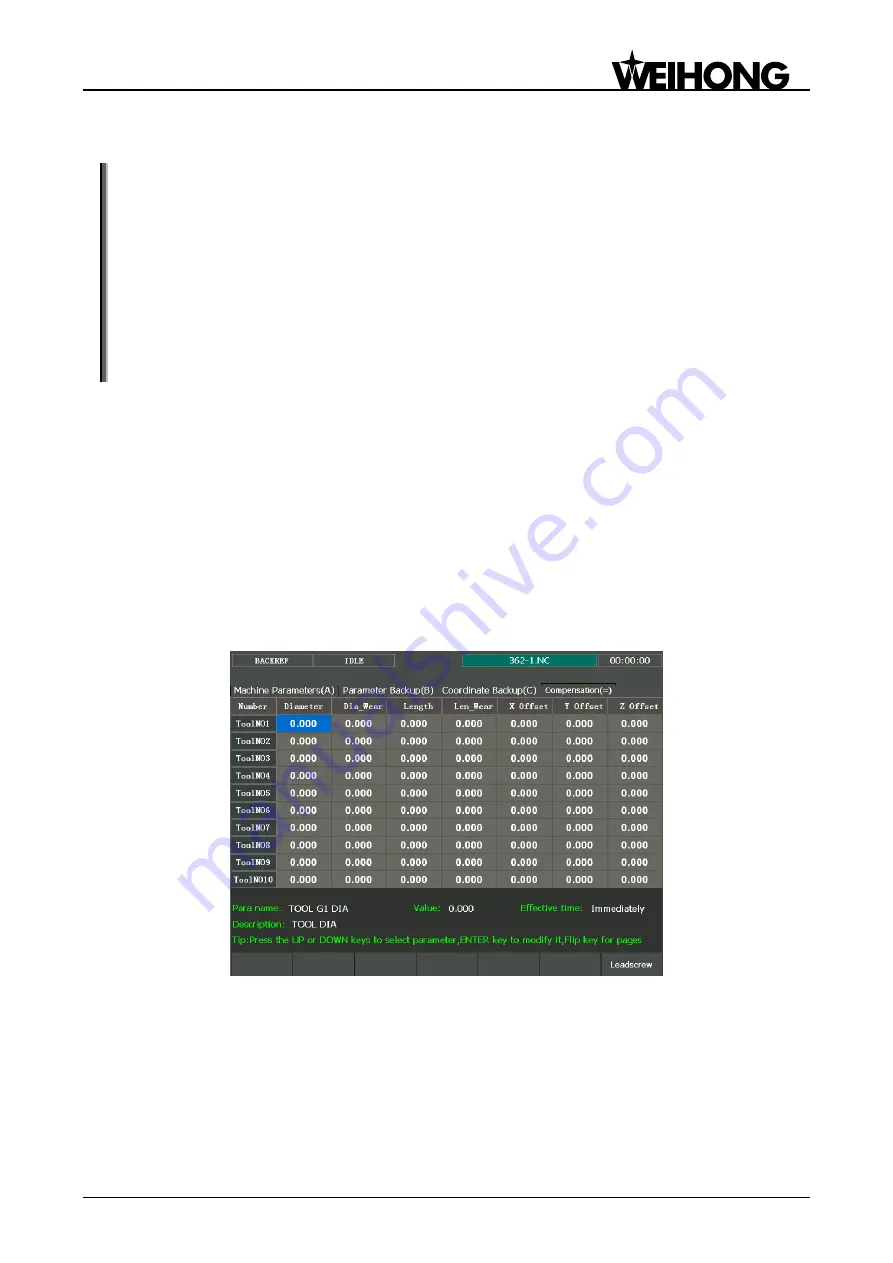
Input the new tool parameter values in [Compensation (=)] input interface (as shown in Fig. 3-38) if
tool nose radius is altered after tool wear, tool sharpening or tool change, avoiding the trouble to modify
the programmed processing procedure.
Fig. 3-38 Tool parameters screen
To make tool compensation (including tool diameter compensation and tool length compensation)
effective, parameter ―4500 turn on radius compensation‖ should be set as ―Yes‖. Code G43 (positive
offset) and G44 (negative offset) are used for tool length compensation; G41 (left compensation) and
G42 (right compensation) for tool radius compensation; G40 (cancel tool radius compensation) and G49
(cancel tool length compensation) are used for canceling tool compensation.
Only when tool compensation codes and G00/G01 are used together can the tool compensation be
enabled.


