


6
Inverter Model and Accessories Identification
6-4 | CFW700
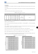
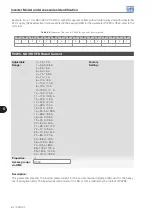
Example: For a 10 A, 380...480 V CFW700, with RFI suppressor filter, without safety relay and without external
24 V supply, the hexadecimal code presented in the keypad (HMI) for the parameter P0029 is C544 (refer to the
).
Table 6.5:
Example of the code at P0029 for a specific inverter model
15
14
13
12
11
10
9
8
7
6
5
4
3
2
1
0
1
1
0
0
0
1
0
1
0
1
0
0
0
1
0
0
C
5
4
4
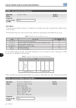
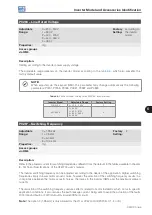
P0295- ND/HD VFD Rated Current
Adjustable
Range:
0 = 2 A / 2 A
1 = 3.6 A /3.6 A
2 = 5 A / 5 A
3 = 6 A / 5 A
4 = 7 A / 5.5 A
5 = 7 A / 7 A
6 = 10 A / 8 A
7 = 10 A / 10 A
8 = 13 A / 11 A
9 = 13.5 A / 11 A
10 = 16 A / 13 A
11 = 17 A / 13.5 A
12 = 24 A / 19 A
13 = 24 A / 20 A
14 = 28 A / 24 A
15 = 31 A / 25 A
16 = 33.5 A / 28 A
17 = 38 A / 33 A
18 = 45 A / 36 A
19 = 45 A / 38 A
20 = 54 A / 45 A
21 = 58.5 A / 47 A
22 = 70 A / 56 A
23 = 70.5 A / 61 A
24 = 86 A / 70 A
25 = 88 A / 73 A
26 = 105 A / 86 A
27= 105 A / 88 A
28= 142 A / 115 A
29= 180 A / 142 A
30= 211 A / 180 A
Factory
Setting:
Properties:
ro
Access groups
via HMI:
READ
Description:
This parameter presents the inverter rated current for the normal overload regimen (ND) and for the heavy
overload regimen (HD). The inverter operation mode, if it is ND or HD, is defined by the content of P0298.
Содержание CFW700
Страница 2: ......
Страница 4: ......
Страница 8: ...Summary...
Страница 34: ...2 General Information 2 4 CFW700...
Страница 38: ...3 About the CFW700 3 4 CFW700...
Страница 56: ...7 Starting up and Settings 7 4 CFW700...
Страница 58: ...8 Available Control Types 8 2 CFW700...
Страница 78: ...10 VVW Control 10 8 CFW700...
Страница 158: ...13 Digital and Analog Inputs and Outputs 13 28 CFW700...
Страница 184: ...16 Read only Parameters 16 12 CFW700...