


12
Functions Common to all the Control Modes
12-12 | CFW700
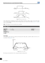
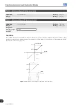
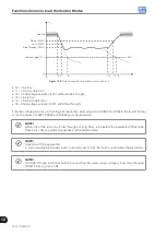
12.5.3 V VW or V/f Ride-Through
The Ride-Through function in the V/f mode will disable the output pulses (IGBT) of the inverter as soon as the input
voltage reaches a value below the undervoltage level. The undervoltage fault (F021) does not occur and the DC
link voltage will decrease slowly until the line voltage returns.
If the line takes too long to return (more than 2 seconds), the inverter may indicate F021 (DC link undervoltage).
If the line voltage returns before a fault, the inverter will enable the pulses again, imposing the speed reference
instantaneously (as in the Flying Start function) and applying a voltage ramp with the time defined by P0331. Refer
to the
and
DC Link Voltage
F021 Level
Output Pulses
Output Voltage
0 V
Output Speed
(P0002)
0 rpm
Line Returns
P0332
Enabled
Disabled
P0331
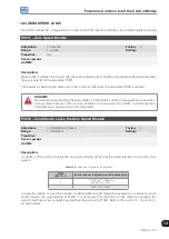
Disabled
Output Pulses
Time adjusted in
P0332
Output Voltage
0 V
Output Speed
(P0002)
0 rpm
Line Returns
Enabled
P0332
P0331
F021 Level
DC Link Voltage
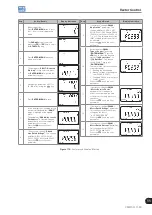
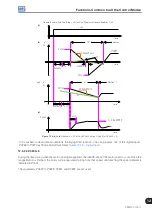
(a) with the line returning before the time adjusted in P0332
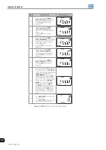
(b) with the line returning after the time adjusted in P0332,
but before 2 s (for P0332 ≤ 1 s), or before 2 x P0332
(for P0332 > 1 s)
Figure 12.5 (a) and (b):
Ride-Through actuation in V/f or VVW modes
The actuation of the Ride-Through function can be visualized at the outputs DO1/RL1, DO2, DO3, DO4 and/or
DO5 (P0275 to P0279), provided that they have been programmed in “22=Ride-Through”.
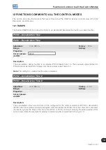
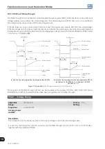
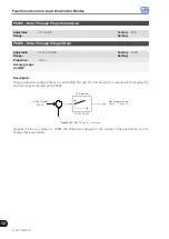
P0331 – Voltage Ramp
Adjustable
Range:
0.2 to 60.0 s
Factory
Setting:
2.0 s
Properties:
V/f and VVW
Access groups
via HMI:
Description:
This parameter sets the necessary time for the output voltage to reach the rated voltage value.
It is used by the Flying Start function as well as by the Ride-Through function (both in V/f or VVW modes),
together with the parameter P0332.
Содержание CFW700
Страница 2: ......
Страница 4: ......
Страница 8: ...Summary...
Страница 34: ...2 General Information 2 4 CFW700...
Страница 38: ...3 About the CFW700 3 4 CFW700...
Страница 56: ...7 Starting up and Settings 7 4 CFW700...
Страница 58: ...8 Available Control Types 8 2 CFW700...
Страница 78: ...10 VVW Control 10 8 CFW700...
Страница 158: ...13 Digital and Analog Inputs and Outputs 13 28 CFW700...
Страница 184: ...16 Read only Parameters 16 12 CFW700...