


13
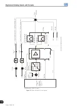
Digital and Analog Inputs and Outputs
13-14 | CFW700
13.1.4 Digital Outputs / Relays
The CFW700 has one digital output relay and 4 open collector outputs available in the control board as standard.
The next parameters configure the functions related to those outputs.
P0013 – DO5 to DO1 Status
Adjustable
Range:
Bit 0 = DO1
Bit 1 = DO2
Bit 2 = DO3
Bit 3 = DO4
Bit 4 = DO5
Factory
Setting:
Properties:
ro
Access groups
via HMI:
READ or I/O
Description:
By means of this parameter it is possible to visualize the status of the control board 5 digital outputs (DO1 to
DO5).
The indication is done by means of the numbers “1” and “0”, representing respectively the “Active” and “Inactive”
states of the outputs. The state of each output is considered as one digit in the sequence where DO1 represents
the least significant digit.
Example: In case the sequence
00010010
is presented on the keypad (HMI), it will correspond to the following
status of the DOs:
Table 13.7:
Digital outputs status
DO5
DO4
DO3
DO2
DO1
Active
(+24 V)
Inactive
(0 V)
Inactive
(0 V)
Active
(+24 V)
Inactive
(0 V)
P0275 – DO1 Function (RL1)
P0276 – DO2 Function
P0277 – DO3 Function
P0278 – DO4 Function
Содержание CFW700
Страница 2: ......
Страница 4: ......
Страница 8: ...Summary...
Страница 34: ...2 General Information 2 4 CFW700...
Страница 38: ...3 About the CFW700 3 4 CFW700...
Страница 56: ...7 Starting up and Settings 7 4 CFW700...
Страница 58: ...8 Available Control Types 8 2 CFW700...
Страница 78: ...10 VVW Control 10 8 CFW700...
Страница 158: ...13 Digital and Analog Inputs and Outputs 13 28 CFW700...
Страница 184: ...16 Read only Parameters 16 12 CFW700...