6.
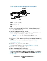
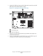
Using the needle-nose pliers, gently compress the top and bottom sides of the APH
retainer and withdraw it from the control port.
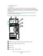
Figure 2–40: Removing the APH retainer clip
Gently compress the retainer at these locations to remove it from the control port
7.
Remove the O-ring retainer from the inlet end of the column-stabilizer-inlet tubing and
connect the inlet tubing to port 6 of the sample manager injection valve.
Note:
For installation instructions, see
8.
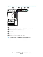
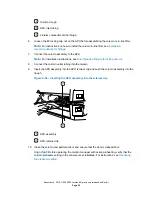
Route the column-stabilizer-inlet tubing behind the hinge of the fluidics compartment door
in the sample manager and into the slot that leads to the column trough.
Figure 2–41: Routing the column-stabilizer-inlet tubing
Column trough
Column-stabilizer-inlet tubing
Fluidics compartment door hinge
9.
Close the fluidics compartment door.
10. Pull the column fitting away from the column stabilizer to access the right-side screw.
December 4, 2019, 715005052 Version 02 (previously released as Rev.B)
Page 57

