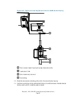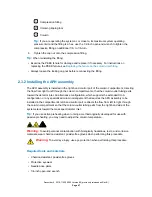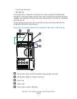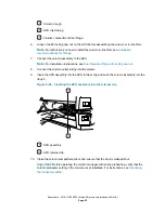
D-sub receptacle on rear of column heater
9.
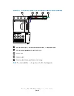
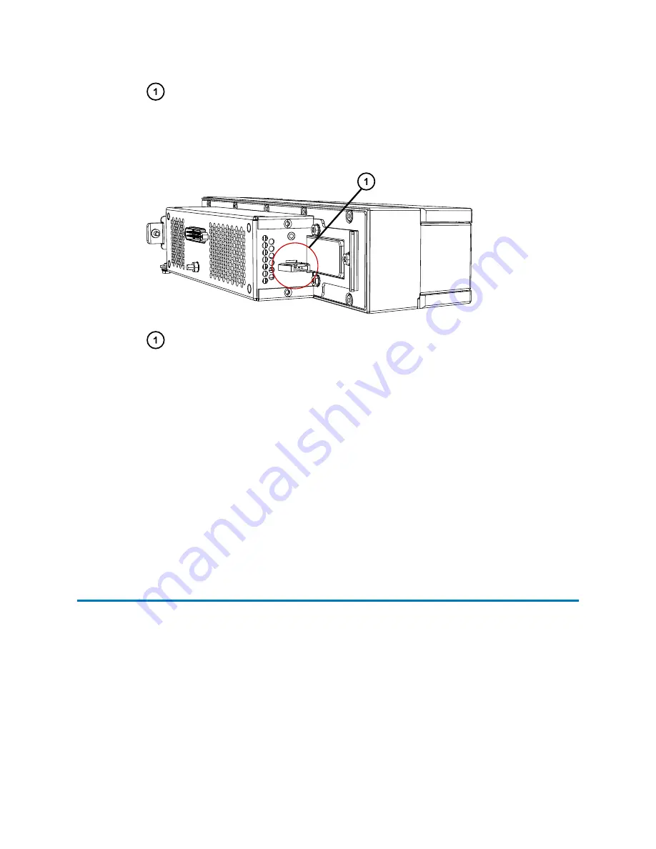
If you installed the leak sensor in the MS-bracket drip tray, insert the leak-sensor cable's
connector into the receptacle located on the rear, left-hand side of the column heater.
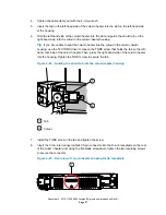
Figure 2–26: Leak-sensor receptacle on the rear, left-hand side of the column heater
Leak-sensor receptacle
10. Swing the column heater into its operating position.
11. Open the column compartment door.
12. Reinstall the APH assembly into the left-hand control port.
Requirement:
You must reconnect and reinstall the column components so that the APH
assembly is installed in the left-hand control port. Doing so allows the flow to go from left to
right within the column compartment, and the column-outlet tubing to exit through the slot
in the column heater door, near the mass spectrometer inlet.
13. Reconnect the APH inlet tubing and reinstall the column components.
14. Connect the column-outlet tubing to the column and to the mass spectrometer inlet
according to the instructions provided with the instrument.
2.3 Column compartment plumbing connections
The standard, active pre-heating configuration of the CH-A module connects a column directly to
the sample manager's injection valve via an APH assembly installed in the compartment.
An alternate configuration, supporting passive pre-heating, connects a column directly to the
sample manager's injection valve via a column-stabilizer assembly installed in the compartment.
You can install an optional column in-line filter before the column.
The topics in this section convey instructions for making the column tubing connections. For
instructions explaining how to install a column in-line filter, see the document
ACQUITY UPLC
Column In-Line Filter Unit Installation Instructions
.
When making column tubing connections, heed these warnings:
December 4, 2019, 715005052 Version 02 (previously released as Rev.B)
Page 38


