55
warmhaus.co.uk
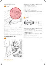
5.12. Outlet Manifold Replacement
CAUTION
Please follow the steps listed in replacement of components – FIRST STAGE
1. Refer to the Draining the Boiler CH and DHW circuit section
2. Remove the diverter valve actuator and place safely within the boiler.
3. Remove the flow pipe from the outlet manifold
4. Disconnect the CH flow and DHW isolation valve connections from
underneath the boiler
5. Remove the LHS plate heat exchanger securing screw
6. Remove the outlet manifold securing screw at the bottom of the boiler
and lift the manifold up and out of the boiler
7. Fit the new outlet manifold in reverse order
8. Re-pressurize the boiler and bleed all excess air.
9. Re-connect the diverter valve actuator.
Please follow the step listed in replacement of components FINAL STAGE.
5.13. Water Pressure Switch Replacement
CAUTION
Please follow the steps listed in replacement of components – FIRST STAGE.
1. Refer to draining the boiler CH circuit section.
2. Remove the electrical connector from the water pressure sensor and
unscrew the sensor from the housing.
3. Ensure the housing is clean and replace the gasket if required.
4. Fit the new water pressure sensor and re-connect the electrical
connector.
5. Re-pressurize the boiler and bleed all excess air.
Please follow the step listed in replacement of components FINAL STAGE.
5.14. 3 Bar Safety Valve Replacement
CAUTION
Please follow the steps listed in replacement of components – FIRST STAGE.
1. Refer to the Draining the Boiler CH circuit section
2. Release the set screw holding in the PRV.
3. Undo the connection from the PRV to the copper stub pipe
4. Gently pull the PRV forward away from the boiler to remove.
5. Ensure the new PRV sealing O-ring is free from damage and is suitably
greased.
6. Push the PRV into the hydraulic housing and ensure it correctly locates.
7. Tighten up the set screw and check the fiber gasket for the copper stub
pipe is in good condition, if not replace and re-connect the PRV copper
stub pipe back to the PRV.
8.
replacement.
9. Re-pressurize the boiler and bleed all excess air.
Please follow the step listed in replacement of components FINAL STAGE.
5.15. DHW Flow Sensor Replacement (for combi boilers
only)
CAUTION
Please follow the steps listed in replacement of components – FIRST STAGE.
1.
2. Remove the electrical connection.
3. Transfer the electrical connection to the new sensor.
4. Clip the new sensor back into place.
Please follow the step listed in replacement of components FINAL STAGE.
5.16. DHW Plate Heat Exchanger Replacement (for
combi boilers only)
CAUTION
Please follow the steps listed in replacement of components – FIRST STAGE.
1. Refer to Draining the Boiler CH circuit and DHW circuit.
2. Remove the 2 x Allen screws securing the plate heat exchanger to the
boiler manifold.
3. Carefully push back the plate heat exchanger and lift clear of the boiler,
ensure suitable protection to the electrics due to any dripping water
from the plate heat exchanger.
4. Replace the O-ring seals and lift the plate heat exchanger back into the
boiler.
5.
plate heat exchanger.
6. Tighten up the 2 x Allen key screws and refill the boiler, then test for
leaks.
Please follow the step listed in replacement of components FINAL STAGE.
Содержание EWA 2525C
Страница 1: ...CONDENSING COMBI BOILERS INSTALLATION SERVICE MANUAL EWA 2525C 25 kW EWA 2530C 30 kW...
Страница 2: ......
Страница 3: ...3 warmhaus co uk...
Страница 28: ...28 warmhaus co uk 3 16 Ewa Combi Boiler Wiring Diagram Wiring Diagram RISK OF ELECTRIC SHOCK 0100_00 W211130...
Страница 57: ...57 warmhaus co uk...

