17
warmhaus.co.uk
3.9. Installation with Horizontal Flue Sets
Connecting Horizontal Concentric Flue Set to the System Boiler, (original
diameter DN 60/100 mm)
Since your boiler is hermetic model, it takes air from exterior and discharges
exhaust gases created as the result of burning through the same flue
group. In order to prevent emission of excessively harmful exhaust gases,
flue usage and installation is very important, therefore warnings should be
taken into consideration when flue connections are being performed.
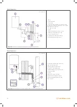
1. 90° Elbow
2. Ø100 Sealing Gasket
3. Ø60 Sealing Gasket
4. Centralizer
5. External Flue Pipe
6. Internal Wall Plate
7. External Wall Plate
8. Internal Flue Pipe
9. Grill
10. Neoprene Gasket
11. Screws
12. Inspection Cap (Fresh Air)
13. Inspection Cap (Gas)
1. 90° elbow
2. Inspection Cap (Gas)
3. Inspection Cap (Fresh Air)
4. Screws
5. Flange Gasket
6. Flange Gasket Screw
7. Neoprene Gasket
8. Ø100 Sealing Gasket
9. Ø60 Sealing Gasket
10. Centralizer
11. Internal Flue Pipe
12. Internal Flue Pipe
13. Internal Wall Plate
14. External Wall Plate
15. Grill
• Loosen the Flange Gasket Screw (6) and remove it from the elbow (1)
• Put the Neoprene Sealing Gasket (7) under the flange and secure it with
4 screws (6 and see Picture A)
• Place the flue elbow (90°) (1) press down and tighten the screw (6) to
secure the flue elbow (see picture B)
• Fit the outer and inner wall flanges (13-14) on the terminal pipe (12)
• Connect flue to the boiler, positioning the seals correctly (picture C).
Seal the flue into the wall with silicone or sand + cement and cover with
Wall Seals provided.
0035_00.D210125
0036_00.D200813
Содержание EWA 2525C
Страница 1: ...CONDENSING COMBI BOILERS INSTALLATION SERVICE MANUAL EWA 2525C 25 kW EWA 2530C 30 kW...
Страница 2: ......
Страница 3: ...3 warmhaus co uk...
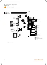
Страница 28: ...28 warmhaus co uk 3 16 Ewa Combi Boiler Wiring Diagram Wiring Diagram RISK OF ELECTRIC SHOCK 0100_00 W211130...
Страница 57: ...57 warmhaus co uk...

