52
warmhaus.co.uk
5. SERVICING & PART REPLACEMENT
5.1. Replacement of Components - First Stage
CAUTION
• Isolate the boiler from the electric supply isolation point
• Carry out electrical safe isolation to the current standard set by the local
regulator
•
the boiler (yellow handle)
• Remove the boiler front cover by unscrewing the 2 x self-tapping screws
located under the boiler at the front section.
• Release the retaining latch situated on the left-hand side of the front
control fascia.
• Gently drop down the front panel fascia into the service position.
• Always ensure caution not to damage any electric cable or connections
whilst working on the boiler.
5.2. Replacement of Components - Final Stage
CAUTION
After replacing any internal component or any component that requires
the front casing removal please follow all gas safety legislation set by your
local governing gas body or regulator for essential checks when working
on a gas appliance and Warmhaus require that you carry out the following
checks as well as your industry required safety checks e.g. 26/9 checks.
• Appliance gas tightness test/test disturbed joints with LDF
• Gas rate (where at all possible)
• Combustion Check
• Ensure the correct fitting of the front casing
• Flue inspection
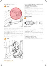
5.3. Draining The Boiler / CH Circuit
CAUTION
Isolate the boiler from the electric supply isolation point.
Carry out electrical safe isolation to the current standard set by the local
regulator.
Isolate the CH flow and return isolation valves located under the boiler.
Ensure the auto air vent cap is open
Connect a suitable hose to the boiler drain point located at the rear of the
pump under the boiler.
Ensure your drain hose is located in a suitable location for the water in the
boiler to drain safely
Open the boiler drain point and release the heating system water until the
boiler is fully drained.
When required close the drain point, remove the hose and re-fill the boiler
and run Deareation mode.
5.4. Draining The Boiler / DHW Circuit (only for combi
boilers)
CAUTION
Isolate the boiler from the electric supply isolation point.
Carry out electrical safe isolation to the current standard set by the local
regulator.
Isolate the cold-water inlet isolation valve located under the boiler.
Open the lowest DHW tap or outlet and very slightly loosen the DHW
connection nut under the boiler and a hissing sound should be heard
allowing the water in the DHW circuit to exist the boiler through the open
outlet.
When required close the DHW outlet and check the disturbed gasket on the
DHW connection nut and replace if required, tighten the DHW connection
nut under the boiler.
0082_00.W210120
Содержание EWA 2525C
Страница 1: ...CONDENSING COMBI BOILERS INSTALLATION SERVICE MANUAL EWA 2525C 25 kW EWA 2530C 30 kW...
Страница 2: ......
Страница 3: ...3 warmhaus co uk...
Страница 28: ...28 warmhaus co uk 3 16 Ewa Combi Boiler Wiring Diagram Wiring Diagram RISK OF ELECTRIC SHOCK 0100_00 W211130...
Страница 57: ...57 warmhaus co uk...


