background image

60

warmhaus.co.uk

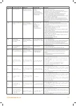
Error Code

Description of the Error

Malfunction

Probable Cause

Solution(s)

E 19

Water flow selection with 
water flow meter input 
reading

Lack of domestic heating 
water on request

Wrong parameters settled 
on TsP menu

1-) Call for authorised service at first
2-) Only authorised service must adjust TsP Parameter P01=0 with 
defalut value

E 20

CH Overtemperature, 
Temperature Central 
Heating > TSP 81 value °C

Boiler does not work, E81 
error code flashing on the 
screen

> Lack of water on the 
system
> Pump blockage
> Pump failiure
> Pump harness
> Installation blockage

1-) RESET boiler at first check if problem removed
2-) Check boiler central heating valves are open if they are closed 
open of all 
3-) Check all radiator valves are open if they are closed open of all 
minimum 3 meters of radiator must be open
4-) RESET boiler and check if problem removed
5-) Call for authorised service at first
6-) Check Pump operation if the pump circuation through the heat 
exchanger is enough
7-) Check intermittent contacts on harness carefully specially Pump 
and PWM cable and speciallypump main supply connector and 
specially pump main connector, measure voltage from connectors 
8-) Check if there is air on the heat exchanger or system, remove air if 
any to do that activate deareation mode.
9-) Check heat exchanger water path againts clogging
10-) Installation water path againts clogging
11-) Reset & Restart boiler 

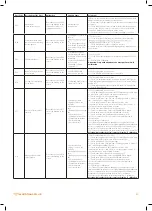
E 21

Delta Temperature Central 
Heating flow and Return > 
TSP 82 value °C

Boiler does not work, E21 
error code flashing on the 
screen

> Lack of water on the 
system
> Pump blockage
> Pump failiure
> Pump harness
> Installation blockage

1-) RESET boiler at first check if problem removed
2-) Check all radiator valves are open if they are closed open of all 
minimum 3 meters of radiator must be open
3-) RESET boiler and check if problem removed
4-) Call for authorised service at first
5-) Check Pump operation if the pump circuation through the heat 
exchanger is enough
6-) Check intermittent contacts on harness carefully specially Pump 
and PWM cable and speciallypump main supply connector and 
specially pump main connector, measure voltage from connectors 
7-) Check if there is air on the heat exchanger or system, remove air if 
any to do that activate deareation mode.
8-) Check heat exchanger water path againts clogging
9-) Installation water path againts clogging
10-) Reset & Restart boiler 

E 28

Maximum allowed 
consecutive lock-out reset 
reached

Usable RESET number 
reached.

Too many consecutive 
lock-out failures (followed 
by reset) due to other 
possible causes

1-) Removing power supply reset will be allowed 
2-) Check the root cause of Error code to solve 
3-) If fault still persists call for authorised service

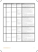
E 37

Low voltage anomaly

Boiler does not work, E37 
error code flashing on the 
screen

Low voltage < 165 VAC +/- 
5% on the supply network 
operation mode
OR
During Au-TO calibration 
mode < 182 VAC +/- 5%

1-) Call for Electrical supply network provider
2-) Error will remove if supply voltage > 170 VAC +/- 5% 
3-) If you seen seen this E37 during calibration calibration can not be 
complete unless supply voltage > 188 VAC +/- 5% 

E 40

Wrong network frequency 
survey

Boiler does not work, E40 
error code flashing on the 
screen

Wrong frequency survey 
out of tolererance 50 Hz 
+/- 5% on the supply net 
work

1-) Call for Electrical supply network provider
2-) Error will remove if supply frquency 50 Hz +/- 5% 

E 41

Loose of flame more than 
6 successive times

Boiler does not work, E41 
error code flashing on the 
screen

> Too many domestic heat 
water request in short 
period ( 1 min )
> Low gas pressure

1-) Call for authorised service at first
2-) Check intermittent contacts on harness carefully
3-) Check gas supply pressure must be 20-17 mbar. Gas pressure must 
be in between on this values while boiler on operational
4-) Check wrong flue OR flue gas blockage 
5-) Check recirculation ( flue gas leak ) from flue gas path to fresh air 
side, check flue gas sealings specially
6-) Check any problems on the ionisation electrode, (like 
condensation, rust etc.), and control poistioning of the electrode, if 
electrode poistion wrong calibrate electrode.
7-) Check if the heat exchanger coils clogged or not
8-) Check for condensation on the cabling AND/OR on board
9-) Check earth connection between board and electrode
10-) Check electrode cabeling between board and electrode
11-) Check combustion CO

2

 or O

2

 values on HI and LO mode at 

sweeper mode. 
12-) Perform Au-To calibration.
13-) if not successfull. Replace board, but use original service key from 
the board dismantled to keep original parameters and calibration 
points. If original service key not used aslo adjust P15 releated to the 
default value of boiler power and Perform Au-To calibration.
14-) if not successfull replace gas valve, and Perform Au-To calibration. 

Attention: Only authorised service must perform Au-To calibration

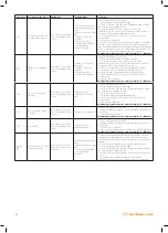
E 42

Buttons anomaly

Boiler does not work, E42 
error code flashing on the 
screen

Wrong parameters settled 
on TsP menu

1-) Call For service
2-) Service must adjust TsP Parameter P67 with defalut value
3-) Check button pads or swithches are functional
4-) if not successfull. Replace board, but use original service key from 
the board dismantled to keep original parameters and calibration 
points. If original service key not used aslo adjust P15 releated to the 
default value of boiler power and Perform Au-To calibration.

Attention: Only authorised service must perform Au-To calibration

Содержание EWA 2525C

Страница 1: ...CONDENSING COMBI BOILERS INSTALLATION SERVICE MANUAL EWA 2525C 25 kW EWA 2530C 30 kW...

Страница 2: ......

Страница 3: ...3 warmhaus co uk...

Страница 4: ...ation of its operation The installer is legally required to complete a commissioning checklist as a means of complying with the appropriate Building Regulations England and Wales All installations mus...

Страница 5: ...n Wiring Diagram 31 4 COMMISSIONING 32 4 1 Display Function 32 4 1 1 SET Transparent Parameters Menu TSP 32 4 1 2 Parameters 33 4 1 3 Parameter Information 38 4 2 Service Mode 38 4 3 CO CO2 Combustion...

Страница 6: ...of all statutory regulations These appliances are CE certified for safety and performance and therefore must in no way be altered or have any device or controls fitted unless it is approved in this d...

Страница 7: ...read the instructions supplied with the boiler For installation of this appliance in Ireland the following regulations must always be followed ECTI National rules for electrical installations Irish S...

Страница 8: ...18 0 92 1 15 Gas Rate Min 0 37 0 11 0 37 0 11 8 7 9 2 10 10 5 8 7 9 2 10 10 5 C02 Minimum Power AUTO CALIBRATION ONLY 8 6 9 4 10 10 5 8 6 9 4 10 10 5 C02 Ignition Power AUTO CALIBRATION ONLY 8 8 9 3...

Страница 9: ...form to all current building regulations Part L1A This can be an exception for a single story open plan dwelling where the living area is more than 70 of the useable floor area in this case this zone...

Страница 10: ...n Vessel 17 Radiator Inlet Return Pipe 18 Gas Inlet Pipe 19 CH Return NTC Sensor 20 Pump 21 DHW Plate Heat Exchanger 22 3 Bar Safety Valve 23 Manometer 24 Tap Water Flow Sensor 25 Gas Valve 26 Heat Ex...

Страница 11: ...to safely adjust any controls on the boiler All roof space installations should comply to BS5410 part 1 roof space installations Storage Do not store any flammable materials around the location of the...

Страница 12: ...detail 2 6 3 Primary system cleaning Debris in the existing heating system can cause damage to the boiler unit correct cleaning has not been carried out 2 7 Electric Supply RISK OF ELECTRIC SHOCK This...

Страница 13: ...mm I Above ground roof or balcony level 300 J 600 K 1200 L 1200 M 1500 N 300 O 50 mm P From a structure on the roof N A Q 300 2 9 Flue Terminal Position H H N M K Q Q D E A B C L F J P G I I Q O Bound...

Страница 14: ...e also displays the pipe centers and correct pipe work layout for the correct installation of the boiler pipe work 3 4 Preparing the Wall Drill Flue Hole ATTENTION When drilling the flue hole ensure t...

Страница 15: ...with a flexible hose supplied with the boiler as per the above image 1 Central Heating Return CH 3 4 thread 2 Domestic Hot Water Inlet DHW 1 2 thread 3 Domestic Hot Water Outlet DHW 1 2 thread 4 Centr...

Страница 16: ...anometer 0 Filling Loop Connection 1 Remove the dust cap and connect to flexible hose to the check valve securely 2 Slowly turn the both valves to the Open position until the pressure gauge reads betw...

Страница 17: ...Neoprene Gasket 11 Screws 12 Inspection Cap Fresh Air 13 Inspection Cap Gas 1 90 elbow 2 Inspection Cap Gas 3 Inspection Cap Fresh Air 4 Screws 5 Flange Gasket 6 Flange Gasket Screw 7 Neoprene Gasket...

Страница 18: ...s provisions must be made for inspection and service requirements Minimum 300 mm square inspection hatches must be fitted The inspection hatch edge must not be fitted more than 1 5 meters away from a...

Страница 19: ...tal length of hermetic flue set should not exceed 10 m with single elbow horizontally Also this total length reduces by 1 m with every 90 elbows or two 45 elbows Maximum 3 pieces of 90 elbow can be us...

Страница 20: ...re the vertical flue terminal is installed level without a slope The vertical flue terminal can be fitted to both flat and pitched surfaces Flue Data WARNING Warmhaus flue pipe technical specification...

Страница 21: ...mhaus co uk Implementation L1 0 3 m L2 0 5 m 45 elbow equivalent length L3 2 0 m L4 0 5 m 45 elbow equivalent length L5 1 0 m L6 1 5 m L Total 6 3 m 6 3 m Lmax 11 m Correct in implementation 0046_00 D...

Страница 22: ...0 mm 45 Elbow 90 Elbow L 170 mm L 130 mm Flat Roof Outlet Part 15311660600124 15311660600125 3 12 Concentric Flue Kits For Condensing Boilers 60 100 mm 500 mm 500 mm 132 5 160 mm 132 5 mm 129 mm 110 m...

Страница 23: ...ay or passageway check that combustion products will not cause a nuisance and that the terminal will not obstruct the passageway 3 If a terminal is less than 2 metres above a balcony above ground or a...

Страница 24: ...nternal diameter 30mm 11 Water Weatherproof insulation 12 Drain cover leaf guard Internal Condensate Pipe Discharge Termination Connection of a condensate discharge pipe up stream of a sink basin bath...

Страница 25: ...eak at plug hole 3 75 mm sink basin bath or shower waste trap 4 Sink basin bath or shower with integral overflow 5 Open end of condensate discharge pipe direct into gully 25 mm min below grating but a...

Страница 26: ...rnal diameter 19 mm 9 Pipe size transition point 10 Minimum internal diameter 30mm 11 Water weather proof insulation External Connections 1 Condensate discharge pipe from boiler 2 Pipe size transition...

Страница 27: ...mm 10 Water weatherproof insulation 11 Fit drain cover leaf guard Internal Condensate Pipe Discharge Termination 1 Condensate discharge pipe from boiler 2 Ground this section of the condensate discha...

Страница 28: ...28 warmhaus co uk 3 16 Ewa Combi Boiler Wiring Diagram Wiring Diagram RISK OF ELECTRIC SHOCK 0100_00 W211130...

Страница 29: ...es on the terminal connector 3 16 2 External Control Connection High Voltage 240 V Installation CAUTION To connect your 240 V external control remove the green link wire on the boiler terminal connect...

Страница 30: ...s voltage connected to the room stat connections on our terminal connector therefore if the system configuration is an SPLAN please follow the above image to ensure that 240v voltage will not be appli...

Страница 31: ...ust not have voltage connected to the room stat position on our terminal connector therefore if the system configuration is a YPLAN you must connect the relay supplied with our boiler as per the above...

Страница 32: ...circle complete on the LCD and release buttons 7 Now you are able to change the parameter Toggle to increase or to decrease to SET PARAMETER VALUE 8 Ones you reach desired value PXX Y press the DHW bu...

Страница 33: ...P06 Maximum CH power 0 100 N A N A P07 Ignition heating ramp time value 1 10 seconds 0 80 60 60 P08 Maximum CH power P10 100 80 80 P09 Maximum DHW power P10 100 82 100 P10 Minimum power 0 P09 0 0 P11...

Страница 34: ...ection 0 1 0 0 0 Low temperature disabled 1 Low temperature enabled Max CH temperature 47 C P22 Flues gas pipe length value 1 1 meter 1 10 1 1 P23 Cycling time pump activation cold zone value 1 1 minu...

Страница 35: ...rst 0 1 0 0 0 Pre heat OFF PrE OFF 1 Pre heat ON PrE On P43 Delay of DHW activation with solar config value 1 1 second 0 30 sec 0 0 P44 Pressure switch selection 0 2 0 0 0 Water pressure switch 1 Wate...

Страница 36: ...A N A P54 Fluxmeter value for DHW request activation value 10 liter minute 10 40 10 l min 15 15 P55 DHW post ventilation time value 1 10 seconds 1 30 sec x 10 3 3 P56 DHW post circulation time value 1...

Страница 37: ...0 0 Push button only 1 Turning knobes with push button P68 B P paramter 1 DO NOT CHANGE 0 255 63 63 P69 B P paramter 1 DO NOT CHANGE 0 255 1 1 P80 Delta TCH slope on CH for check pump blockage 0 disab...

Страница 38: ...Service Mode Designation Ewa Combi Boiler wall hung boilers Object Type model Technical data Mark s of conformity Procedure service mode Ewa Combi Boiler granted by Warmhaus R D Pos No Operation Desc...

Страница 39: ...ve been completed correctly e g gas pressure gas rate flue integrity and re circulation then please run FTF please follow FTF procedure If FTF is not enough for correct emission values please run Auto...

Страница 40: ...table below check to see if the CO2 or O2 is within the tolerances stated Step 4 If the readings are out of the tolerance then adjust the setpoint using the DHW or buttons to increase or decrease the...

Страница 41: ...hin 3 seconds 5 On the screen Au To will be displayed and the boiler will try to make ignition attempts Do not change gas pressure OR touch to the boiler on this stage 6 Flame occurance then boiler wi...

Страница 42: ...y key during this time 5 After the exclamation mark is gone on the combi screen complete the cycle by pressing the DHW buttons use the and buttons to adjust the emission Attention Calibration range is...

Страница 43: ...this calibration process 3 If the Open Therm OT thermostat is connected to the boiler before starting the ESF be sure that OT thermostat is in OFF mode No heat demand via OT thermostat set temp room t...

Страница 44: ...ecreased by 1 13 When 0 is reached the function stops and the boiler exit from the ESF automatically 14 When the boiler exit from the ESF the boiler stays in Winter mode If the ON OFF thermostat bridg...

Страница 45: ...FO MENU In X value shows following information 6 In0 SW version In1 Display of external probe temperature if connected C In2 Display of CH Flow probe temperature C In3 Display of Safety Limit probe te...

Страница 46: ...il the approval circle complete on the LCD and release buttons 3 Be sure that the OFF is dsiplayed on the screen If not press again the MODE and repeat the step above Until OFF symbol shown on the scr...

Страница 47: ...nged 5 Ones you reach the parameter aimed to be changed on the screen press the DHW button to be able to change the parameter value 6 Wait until the approval circle complete on the LCD and release but...

Страница 48: ...when carrying out this check Operate the boiler in maximum output by either running a DHW tap or put the boiler into service mode please see page 38 for instructions Remove the air inlet test point on...

Страница 49: ...k the data shown on the calculator routinely by carrying out a gas rate as per the current gas working practices manually and compare the figures If the App calculator is proven to be accurate and can...

Страница 50: ...ou reach the parameter aimed to be changed on the screen press the DHW button to be able to change the parameter value 6 Wait until the approval circle complete on the LCD and release buttons 7 Now yo...

Страница 51: ...on the screen press the DHW button to be able to change the parameter value 6 Wait until the approval circle complete on the LCD and release buttons 7 Now you are able to change the parameter Toggle...

Страница 52: ...casing Flue inspection 5 3 Draining The Boiler CH Circuit CAUTION Isolate the boiler from the electric supply isolation point Carry out electrical safe isolation to the current standard set by the loc...

Страница 53: ...n electrode to the combustion chamber 5 Remove the electrode 6 Fit the new ignition electrode using a new gasket 7 Ensure the correct distances are maintained between the electrode and burner 8 Reasse...

Страница 54: ...bove checks must also be carried out 11 Re connect all electrical connections to the PCB ensuring they are connected correctly 12 Install the PCB in reverse order as the above instructions 3 2 1 13 Wh...

Страница 55: ...ion 2 Release the set screw holding in the PRV 3 Undo the connection from the PRV to the copper stub pipe 4 Gently pull the PRV forward away from the boiler to remove 5 Ensure the new PRV sealing O ri...

Страница 56: ...5 mm Tolerances Min 4 8 mm Single Electrode IGNITION POSITION THE IGNITION ROD MUST BE CENTERED ON THE SLICES LIKE SHOWN ON THE BURNER SURFACE ELECTRODE POSITION TO THE SURFACE OF THE BURNER A 5 0 mm...

Страница 57: ...57 warmhaus co uk...

Страница 58: ...e screen E 05 temperature sensor faulty screen temperature sensor faulty tolerance replace NTC E 06 screen 7 Check gas supply pressure must be 17 20 Mbar Gas pressure must 8 Check earth connector betw...

Страница 59: ...sensor ressistance if its out of tolerance replace NTC 3 Check cabeling and connectors between FLUE NTC and board 4 Reset Restart boiler E 15 Fan failure feedback supply Boiler does not work E15 error...

Страница 60: ...wed 2 Check the root cause of Error code to solve 3 If fault still persists call for authorised service E 37 Low voltage anomaly Boiler does not work E37 error code flashing on the screen Low voltage...

Страница 61: ...ic board Gas valve failiure 1 Call for authorised service at first 2 Check gas supply pressure must be 20 17 mbar Gas pressure must be in between on this values while boiler on operational 3 Check wro...

Страница 62: ...rculation flue gas leak from flue gas path to fresh air side check flue gas sealings specially 5 Check any problems on the ionisation electrode like condensation rust etc and control poistioning of th...

Страница 63: ...the electrode 5 Check for condensation on the cabling AND OR on board 6 Check earth connection between board and electrode 7 Check electrode cabeling between board and electrode 8 Check combustion CO...

Страница 64: ...orised service must perform Au To calibration E 96 Flue or air suction way blockage Boiler does not work E96 error code flashing on the screen Blokage on flue Blokage on air suction path 1 Call for au...

Страница 65: ...vice Record It is a requirement that the boiler is installed and commissioned to the manufacturers This Commissioning Checklist is to be completed in full by the competent person who commissioned the...

Страница 66: ...ing and Hotwater Industry Council HHIC www centralheating co uk GAS BOILER SYSTEM COMMISSIONING CHECKLIST WARRANTY VALIDATION RECORD Address Zone valves Thermostatic radiator valves m hr or ft mbar m...

Страница 67: ...ed and maintained in line with manufacturers instructions and that the appropriate service interim work record is completed Service provider When completing a service record as below please ensure you...

Страница 68: ...ine support for our assets Gas Emergencies If you smell gas or have accidentally hit the NTS pipeline please call us urgently 0800 111 999 Electricity Emergencies If you spot a potential hazard on or...

Отзывы: