22
1.
Cleaning hole cover
2.
Sensor holder
Fig.
№
. 15
Mounting of emergency fire-extinguishing equipment
5.2.7
Boiler conversion from right-hand design to the left-hand design
−
Remove the grate and pull out the burner with the mixer from the boiler dram (fixtures are as follows:
6 pc screw M10 x 30, 6 pc washer 10.5).
−
From the left side of the base, unscrew the blind flange, insulation, insulation bracket (see Fig. 17) and install
them on the right side (fixtures are as follows: 4 pc screw M10 x 30, 4 pc washer 10.5). Remove the old
mastic. The metal plates between the base and the insulation bracket and between the insulation bracket and
the blind flange must be sealed with mastic.
−
Apply mastic to the burner flange with the mixer and insert the burner into the boiler drum from the left side and
screw it (fixtures are as follows: 6 pc screw M10 x 30, 6 pc washer 10.5).
−
Apply a reasonable quantity of new mastic to the bearing surfaces and mount the grate in the burner. Note:
The cutting of the grate must be always directed to the inlet of the fuel feeder.
Fig.
№
. 16
−
Then proceed according to Chap. 5.2 – Installation procedure.
-
Jacket the boiler (see Chap. 5.2.2).
-
Apply mastic to the fuel feeder flange and connect it to the boiler basement (fixtures are as follows: 4 pc nut
M10, 4 pc washer 10.5). Rotate the motor in such a way that it is in the front when viewing the boiler from the
front.
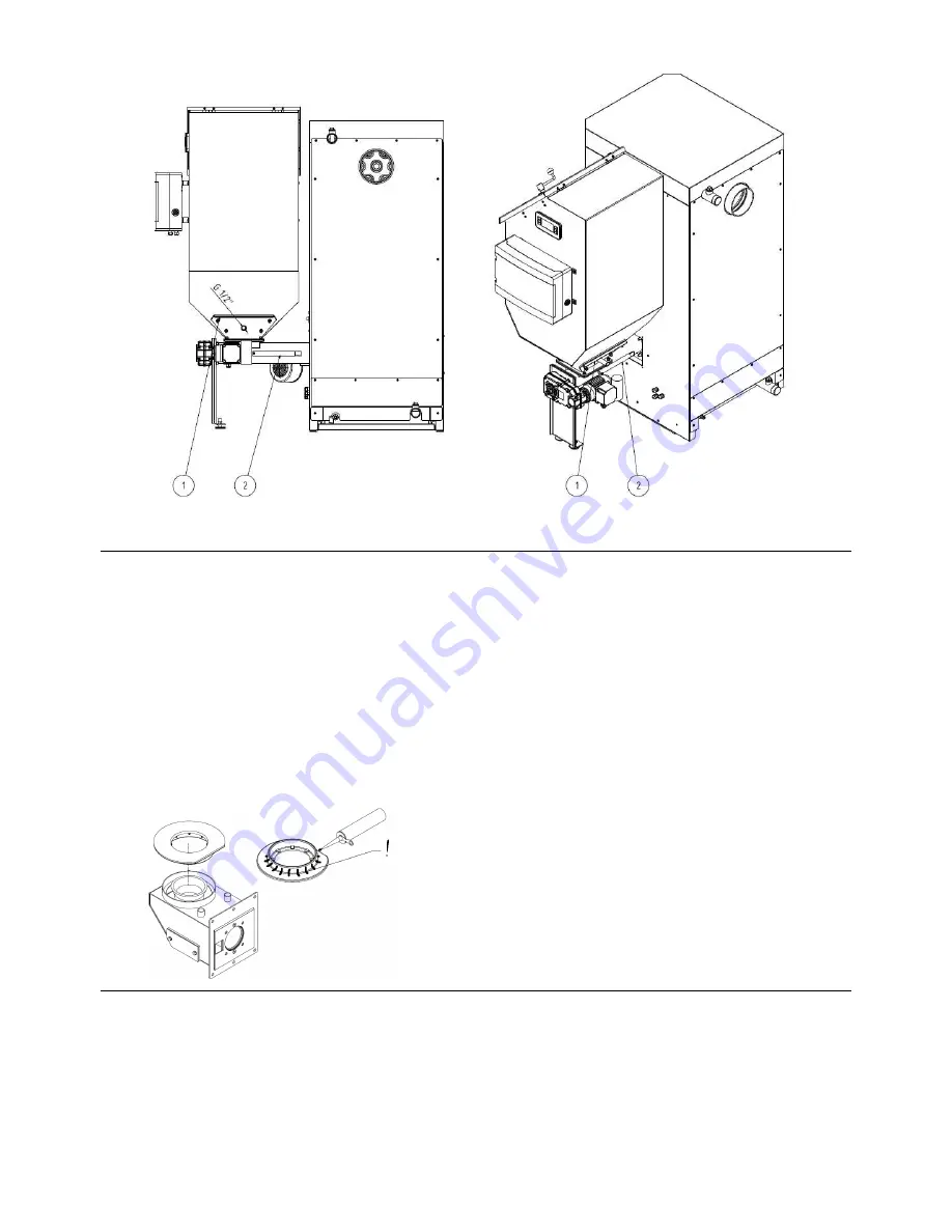
!
Apply the boiler mastic to the marked point and put the
grate on the retort with the mixer. It is necessary to
ensure tightness between the burner and the grate.


