14 Chapter 2 Mechanical Installation
APM 300 Integrated UPS Single Module And Parallel System User Manual
2000
1100
Front view
Main power
cabinet
Switch cabinet
Side view
1100
1200
1930
300
600
Main power
cabinet
Switch
cabinet
Front door
Front view
(front door and back door open)
Main power
cabinet
Switch cabinet
Bottom view
Back door
Cover
Cover
2000
300
1930
600
1100
1200
1100
Front view
Side view
Cover
Cover
Main power
cabinet
Switch
cabinet
Front door
(front door and back door open)
Main power
cabinet
Switch cabinet
Bottom view
Front view
Back door
Main power
cabinet
Switch cabinet
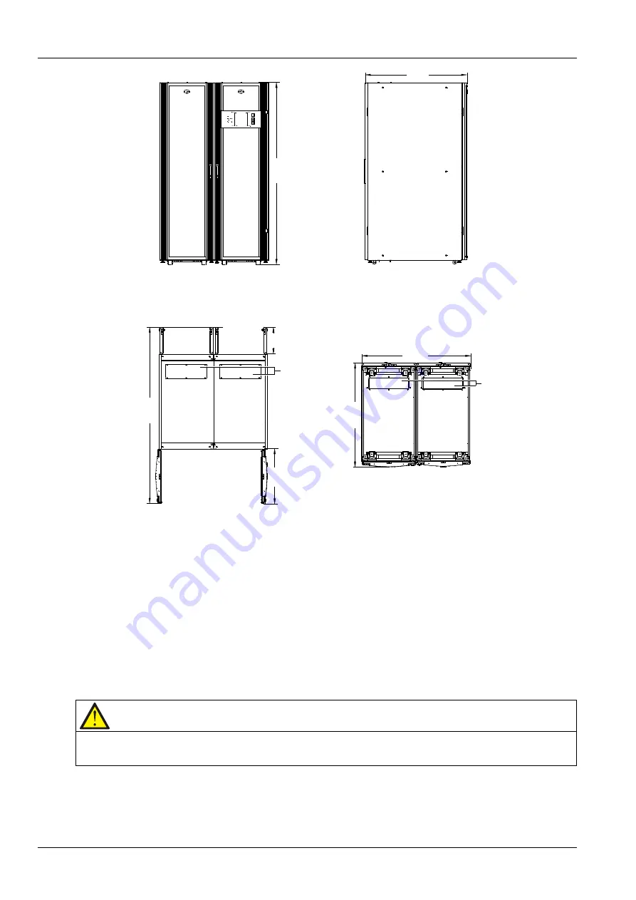
Figure 2-1
UPS installation dimensions (unit: mm)
2.5.2
Mechanical Connection Between Cabinets
The UPS consists of a main power cabinet and a switch cabinet. The two cabinets are shipped separately and
should be connected mechanically at site. The connection procedures are as follows:
1. Place the main power cabinet and switch cabinet closely side by side, with the main power cabinet on the
left side and the switch cabinet on the right side, as shown in Figure 2-2.
2. Adjust the two cabinets to the same height and fix them securely in the position by adjusting the adjustable
feet (see Figure 1-1).
3. Open the front door of the switch cabinet and remove the cover (see Figure 2-2) at the front.
Note
Replace the cover at the front of the switch cabinet after connecting the parallel power cables. Refer to
4. Connect the cabinets with screws: There are two screw holes for cabinet connection (see Figure 2-2) in the
same positions of each beam (totally three beams) on the right side of the main power cabinet. In the
corresponding positions on the left side of the switch cabinet, there are also three beams; and in the same
Содержание Liebert APM 300
Страница 1: ......
Страница 2: ......
Страница 7: ...The Manual Covers The Following Equipment Product Model APM 300 Liebert APM 300...
Страница 9: ......


