Chapter 1 Overview 7
APM 300 Integrated UPS Single Module And Parallel System User Manual
Output switch
Inverter
Rectifier
UPS output
Battery
Automatic inverter switch
Rectifier
Inverter
Automatic inverter switch
Output switch
UPS output
Battery
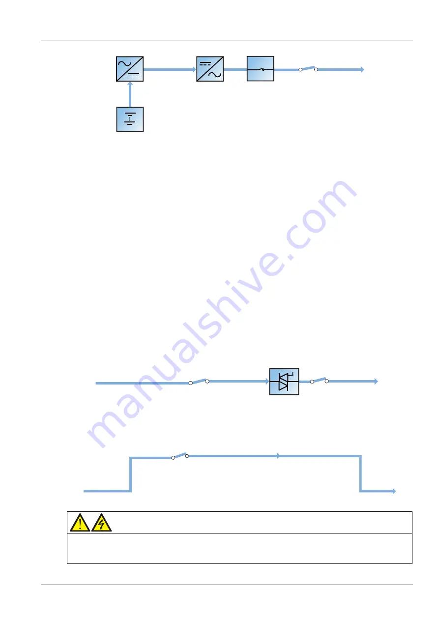
Figure 1-6
Schematic diagram of battery mode
Note: Battery start function is available for switching the UPS on into Battery (charged) mode directly during
mains failure. Thus, the battery power can be used independently to increase the UPS utility.
Automatic restart mode
The battery becomes exhausted following an extended AC mains failure. The inverters shut down when the
battery reaches the EOD voltage. The UPS can be programmed to automatic restart after EOD after a set
variable delay time. This mode and any delay time are programmed by the commissioning engineer.
During the delay time before automatic restart, the UPS charges the battery so as to avoid power interruption
to load in case of a following power failure.
In case the UPS is not programmed to automatic restart, you can use the FAULT CLEAR key to manually start
the UPS.
Bypass mode
As shown in Figure 1-7, during normal mode operation, if the inverters fail, are overloaded or turned off, the
static switch will perform a transfer of the load from the inverters to the bypass source, with no interruption in
power to the load. Should the inverters be asynchronous with the bypass, the static switch will perform a
transfer of the load from the inverters to the bypass, with interruption in power to the load. This is to avoid
paralleling of unsynchronized AC sources. This interruption is programmable but typically set to be less than
3/4 of an electrical cycle, for example, less than 15ms (50Hz) or less than 12.5ms (60Hz).
Bypass input switch
Bypass input
Static switch
Output switch
UPS output
Bypass input
Bypass input switch
Static switch
Output switch
UPS output
Figure 1-7
Schematic diagram of bypass mode
Maintenance mode
As shown in Figure 1-8, if UPS maintenance or repaired is needed, you may use the manual maintenance
bypass switch to transfer the load to the maintenance bypass, with no interruption in power to the load.
Maintenance bypass switch
Bypass input
Maintenance bypass
UPS output
Bypass input
Maintenance bypass switch
Maintenance bypass
UPS output
Figure 1-8
Schematic diagram of maintenance mode
Warning: risk after load transfer to maintenance bypass
After the UPS is transferred to maintenance bypass, the power modules and bypass module are inoperative and the LCD
has no display, only the green indicator of the input SPD shows that the UPS has mains input, but the output terminals
corresponding to closed output distribution switches and the neutral bars are energized.
Содержание Liebert APM 300
Страница 1: ......
Страница 2: ......
Страница 7: ...The Manual Covers The Following Equipment Product Model APM 300 Liebert APM 300...
Страница 9: ......


