


8 Chapter 1 Overview
APM 300 Integrated UPS Single Module And Parallel System User Manual
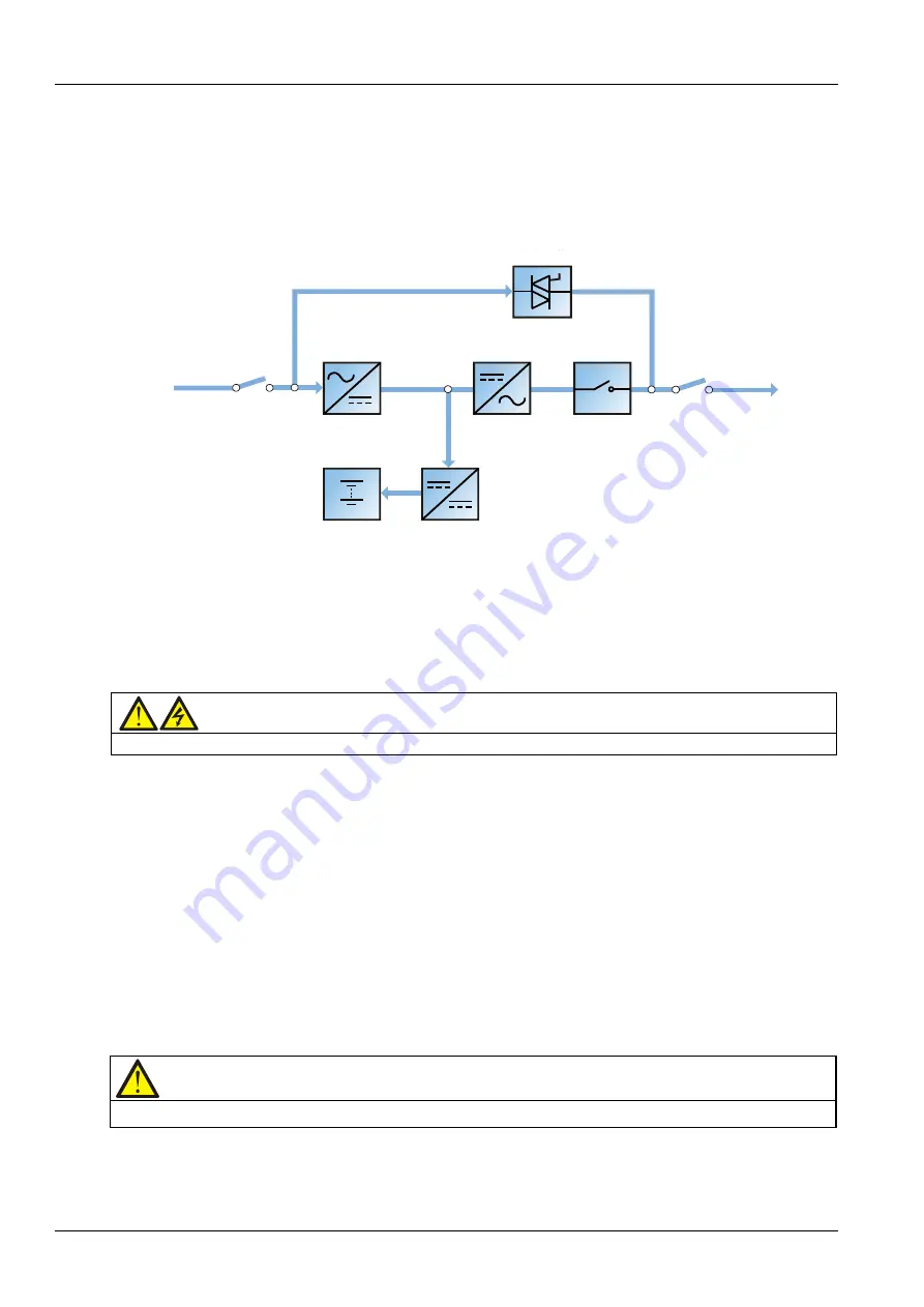
ECO mode
As shown in Figure 1-9, in ECO mode, except for the maintenance bypass switch, all power switches and the
BCB are closed, the system prefers to put the load on the bypass mains to save energy. When the bypass
frequency and voltage are in normal range (settable), the load is supplied by the bypass, with the inverter on
standby. When the bypass frequency and voltage are beyond the normal range, the system will transfer to the
inverter. In ECO mode, the battery is normally charged by the charger.
市电输入
整流器
逆变器
电池
电池充电器
UPS
输出
输入开关
逆变自动开关
Mains input
Input switch
Rectifier
Inverter
Automatic
inverter switch
Output switch
Static switch
Charger
Battery
UPS output
Static switch
Rectifier
Inverter
Automatic
inverter switch
UPS output
Output switch
Charger
Battery
Mains input
Input switch
Figure 1-9
Schematic diagram of ECO mode
The ECO mode configuration requires a different setup in the default menu configuration through the
operator control and display panel.
Operating procedures in ECO mode are the same as those described in
Chapter 5 Operating Instructions
,
except that the load is normally on the bypass mains, the Inverter LED is normally off, and the corresponding
alarm message 'Bypass mode' will appear on the LCD.
Warning
In ECO mode the load is not protected against mains distortion.
Parallel redundancy mode
For higher capacity or higher reliability or both, the outputs of two UPS modules can be programmed for
direct paralleling while a built-in parallel controller in each UPS ensures automatic load sharing.
Dormancy mode
Dormancy mode is designed to maximize the number of the dormant power modules while ensuring load
power, which brings the system efficiency to the greatest extent. The dormancy mode is configured by the
commissioning engineer through the background software. This mode has the following restrictions on the
power module addresses: When there are five power modules, the power module addresses should be 1, 2, 3,
4 and 5 in turn; when there are four power modules, the power module address should be 1, 2, 3 and 4 in turn;
when there are three power modules, the power module addresses should be 1, 2 and 3 in turn; when there
are two power modules, the power module addresses should be 1 and 2 in turn.
Note
In dormancy mode, sudden load change should be avoided, which may cause UPS transfer to bypass mode.
Содержание Liebert APM 300
Страница 1: ......
Страница 2: ......
Страница 7: ...The Manual Covers The Following Equipment Product Model APM 300 Liebert APM 300...
Страница 9: ......


