26 Chapter 4 Operator Control And Display Panel
APM 300 Integrated UPS Single Module And Parallel System User Manual
Chapter 4
Operator Control And Display Panel
This chapter expounds the functions and use of the components on the operator control and display panel of
the UPS, and provides LCD display information, including the LCD screen types, detailed menu messages,
prompt windows and alarm list.
4.1
Introduction
The operator control and display panel of the UPS is located on the front door of switch cabinet. It is the access
point for operator control and monitoring of all measured parameters, UPS and battery status and alarms. The
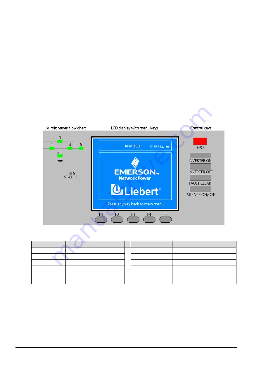
operator control and display panel is divided into three functional areas: mimic power flow chart, LCD display
with menu keys, control keys, as shown in Figure 4-1. The components of the operator control and display
panel are described in Table 4-1.
Figure 4-1
Operator control and display panel
Table 4-1
Description of components on operator control and display panel
Indicator No.
Function
Control key
Function
1
Rectifier indicator
EPO
EPO switch
2
Battery indicator
INVERTER ON
Inverter start switch
3
Bypass indicator
INVERTER OFF
Inverter shutdown switch
4
Inverter indicator
FAULT CLEAR
Fault reset switch
5
Load indicator
SILENCE ON/OFF
Audible alarm silencing switch
6
Status indicator
F1
~
F5
LCD menu keys
4.1.1
LED Indicators
The LED indicators mounted on the mimic power flow chart represent the various power paths and current
UPS operational status. The indicators are described in Table 4-2.
Содержание Liebert APM 300
Страница 1: ......
Страница 2: ......
Страница 7: ...The Manual Covers The Following Equipment Product Model APM 300 Liebert APM 300...
Страница 9: ......


