Chapter 2 Mechanical Installation 15
APM 300 Integrated UPS Single Module And Parallel System User Manual
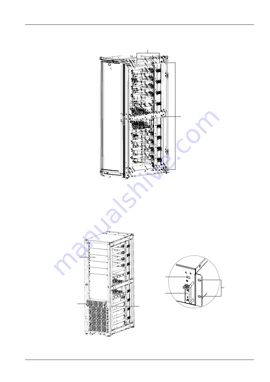
positions of each beam, there are also two screw holes for cabinet connection. Use the accessory M8
×
20
screws to connect the two cabinets through these screws holes, and tighten the connections to 13N.m.
Right side
Screw hole for cabinet connection
Beam
Right side
Figure 2-2
Screw holes for cabinet connection on main power cabinet
2.5.3
Installing Power Module
The installation positions of the power modules are shown in Figure 2-3. Install the power modules from
bottom to top to avoid cabinet tipping due to high gravity center.
Refer to Figure 2-3, and use the following procedures to install the power module:
DIP switch
Ready switch
Fixing hole
A Amplified view
Dummy plate
Power module
A
Figure 2-3
Installing power module
Содержание Liebert APM 300
Страница 1: ......
Страница 2: ......
Страница 7: ...The Manual Covers The Following Equipment Product Model APM 300 Liebert APM 300...
Страница 9: ......


