


80
107774-02 - 4/18
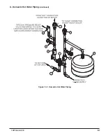
X. Domestic Hot Water Piping
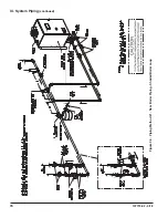
Install the domestic hot water piping as shown in Figure 10.1. Combi connections are ¾” NPT male thread. The
components in this system, and their functions are as follows:
1. ASSE 1070 or ASSE 1017 Listed Tempering Valve (Required) – This boiler is equipped with a control system
that attempts to regulate the DHW outlet temperature to a DHW set point (default set point is 120F – see
Section XIII for more information). As with all water heaters there are inherent limitations on the ability of the
control system to accurately regulate water temperature to this set point under all conditions. Extremely
low draw rates and transitions from heating to DHW are two examples of conditions that can cause the
temperature of water leaving the boiler to significantly exceed the DHW set point. To minimize “spikes” in
DHW temperature, a tempering valve is therefore required. Select and install in accordance with the valve
manufacturer’s instructions and applicable codes. Note that some codes require additional tempering
devices at some of the fixtures as well.
2. Flow Restrictor (Optional) - If domestic hot water is drawn from at a rate in excess of the rating in Table 2.2,
the temperature of the hot water may be too low to be of use. The use of a flow restrictor will help prevent this
problem by limiting the rate at which water can pass through the DHW heat exchanger. If a restrictor is used,
select one having a rating in GPM approximately equal to that shown in Table 2.2 at the desired temperature
rise.
3. Pressure Relief Valve (Required) - Limits the pressure in the domestic hot water piping. Use a valve designed
for DHW service, such as the Watts #3L or #53L. Note that this is a pressure relief valve, not a T&P valve.
Select a valve with a pressure setting less than or equal to 145 psi. Pipe the discharge to a safe location
using piping the same size as the discharge connection on the valve.
4. Hose Bib Valves (Recommended) - These valves permit the DHW plate heat exchanger be periodically
“back flushed” to remove sediment.
5. Globe or Ball Valve (Recommended) - Used to aid in back flushing the heat exchanger and to isolate the
DHW piping if it must be serviced. In addition, the upstream valve may be used to limit the DHW flow if
necessary.
6. Thermal Expansion Tank (Required if a backflow preventer is installed) – If a back flow preventer or check
valve is installed upstream of the cold connection, a thermal expansion tank will prevent the build-up of
pressure in the DHW piping. Use a thermal expansion tank designed for use in potable water service.
7. Unions – Improve serviceability of DHW piping.
NOTICE
DHW feature on this boiler is designed to only to heat potable water (i.e. water from a well or
water utility that is suitable for drinking) having the following characteristics:
a. Hardness less than 200PPM
b. PH between 6 and 8
c. Chloride level less than 80PPM.
Use of water not having these characteristics could result in premature failure of the DHW handling
components in this boiler.
• Internal components near the Hot and Cold connections can be damaged by excessive heat during
soldering. If copper adaptors are mounted directly on the combi, solder adjacent piping to these
adaptors before installing them on the boiler. Failure to do so may cause internal leaks and/or other
damage to the boiler.
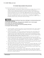
DANGER
Scald Hazard. Under certain conditions this boiler can deliver domestic hot water (DHW)
at temperatures in excess of the DHW set point on the boiler control. An installer-supplied, ASSE 1017 or
ASSE 1070 certified tempering valve is therefore REQUIRED as part of this boiler’s installation.
• Select and install tempering valve in accordance with the valve manufacturer’s instructions and
applicable local codes. In the absence of such codes follow the Uniform Plumbing Code (IAPMO/UPC-1).
Also note that additional tempering valves may be required at the fixtures themselves.
Содержание K2WTC-135
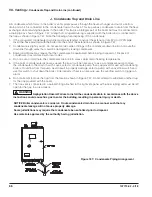
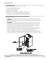
Страница 10: ...10 107774 02 4 18 Figure 4 1 Minimum Clearances To Combustible Construction IV Locating the Boiler continued...
Страница 12: ...12 107774 02 4 18 Figure 5 1 Wall Layout Mounting Hole Location V Mounting The Boiler continued...
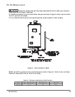
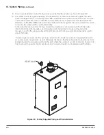
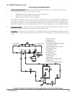
Страница 74: ...74 107774 02 4 18 Figure 9 2 Piping Method 1 Near Boiler Piping Heating Only IX System Piping continued...
Страница 76: ...76 107774 02 4 18 Figure 9 5 Piping Method 1 Near Boiler Piping Shaded Boiler Loop IX System Piping continued...
Страница 81: ...81 107774 02 4 18 X Domestic Hot Water Piping continued Figure 10 1 Domestic Hot Water Piping...
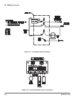
Страница 87: ...87 107774 02 4 18 Figure 11 6 J3 Field Wiring Figure 11 5 4 20 mA EMS Field Wiring XI Wiring continued...
Страница 89: ...89 107774 02 4 18 XI Wiring continued...
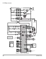
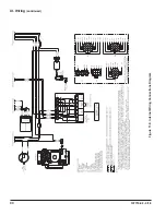
Страница 90: ...90 107774 02 4 18 Figure 11 8 Internal Wiring Connections Diagram XI Wiring continued...
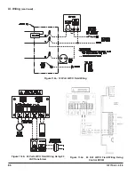
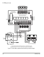
Страница 92: ...92 107774 02 4 18 Figure 11 9 TACO SR504 or Equivalent Zone Panel Wiring Connection Diagram XI Wiring continued...
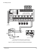
Страница 93: ...93 107774 02 4 18 Figure 11 10 Sage Zone Control Circulator Panel Wiring Connection Diagram XI Wiring continued...
Страница 101: ...101 107774 02 4 18 Lighting and Operating Instructions XII Start Up and Checkout continued...
Страница 142: ...142 107774 02 4 18 XVI Repair Parts continued...
Страница 145: ...145 107774 02 4 18 XVI Repair Parts continued...
Страница 148: ...148 107774 02 4 18 XVI Repair Parts continued...
Страница 150: ...150 107774 02 4 18 XVI Repair Parts continued...
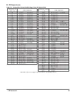
Страница 152: ...152 107774 02 4 18 XVI Repair Parts continued 120 121 122 123 124 125 126 127...
Страница 159: ...159 107774 02 4 18 SERVICE RECORD DATE SERVICE PERFORMED...
Страница 160: ...160 107774 02 4 18 U S Boiler Company Inc P O Box 3020 Lancaster PA 17604 1 888 432 8887 www usboiler net...