


75
107774-02- 4/18
IX. System Piping
(continued)
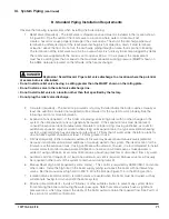
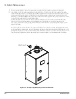
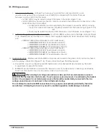
Count all fittings in the boiler loop (shaded in Figure 9.5):
4 90° Elbows
2 Turn in Tee
2 Isolation Valves
Note: Unions, Secondary Connection Tees, and factory supplied fittings are ignored.
Calculate total equivalent length from Table 9.3:
20 ft Straight Pipe + 4 Elbows x 2.8 + 2 Turn in Tee x 5.5 + 2 Valves x 0.7 = 43.6 Equivalent Feet
Since the total equivalent length is less than 60 ft, flow through boiler loop meets requirements in Table 9.1.
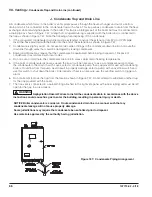
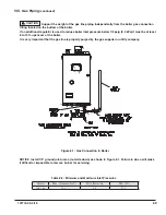
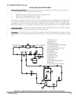
3. Hydraulic Separators – Hydraulic separators serve the same purpose as the closely spaced tees connecting
the boiler and system loops in Figure 9.2. They also generally provide effective connection points for
automatic air elimination devices and an expansion tank. These separators are available from several
sources and may be used in place of the closely spaced tees shown in Figure 9.2. When a hydraulic
separator is used in place of the tees, the 60 ft equivalent length limitation still applies. Select a hydraulic
separator having 1” or larger boiler connections that is designed for the boiler flow rates shown in Table 9.1.
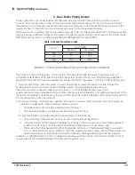
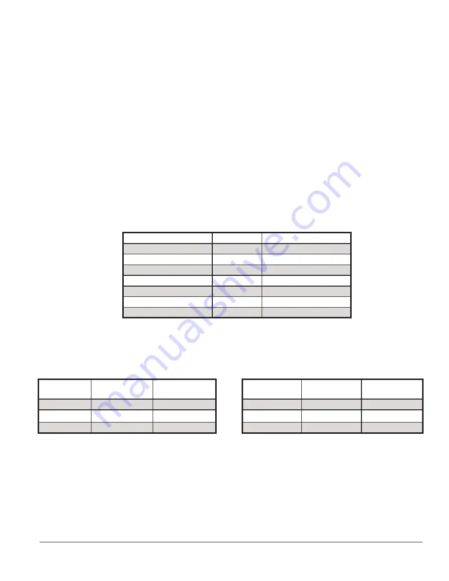
(May Be Used for Copper or Threaded Fittings)
Fitting
Pipe Size
Equivalent Length (ft)
90° Elbow
1”
2.8
45° Elbow
1”
1.4
90° Turn in Tee
1”
5.5
Run of Tee
1”
1.8
Gate Valve (Open)
1”
0.7
Full Port Ball Valve
1”
0.7
Y-Strainer*
1”
7.0
Boiler Model
Approx. Flow
(GPM)
Approx. Rise (°F)
Boiler Model
Approx. Flow
(GPM)
Approx. Rise
(°F)
135
8.6
25
135
8.3
26
150
11.8
23
150
11.1
24
180
11.8
28
180
11.1
29
Table 9.4a: Flow Available with Boiler Loop
Equivalent Length of 30 ft or Less
Table 9.4b: Flow Available with Boiler Loop
Equivalent Length of 60 ft or Less
Table 9.3: Equivalent Lengths for Selected Valves and Fittings
* Based on Cv of 20. Pressure drop through strainers varies widely. 7 ft equiv-
alent length may be assumed for strainers having a published Cv greater than
20.
Содержание K2WTC-135
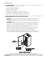
Страница 10: ...10 107774 02 4 18 Figure 4 1 Minimum Clearances To Combustible Construction IV Locating the Boiler continued...
Страница 12: ...12 107774 02 4 18 Figure 5 1 Wall Layout Mounting Hole Location V Mounting The Boiler continued...
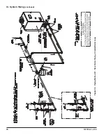
Страница 74: ...74 107774 02 4 18 Figure 9 2 Piping Method 1 Near Boiler Piping Heating Only IX System Piping continued...
Страница 76: ...76 107774 02 4 18 Figure 9 5 Piping Method 1 Near Boiler Piping Shaded Boiler Loop IX System Piping continued...
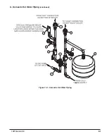
Страница 81: ...81 107774 02 4 18 X Domestic Hot Water Piping continued Figure 10 1 Domestic Hot Water Piping...
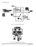
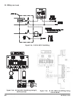
Страница 87: ...87 107774 02 4 18 Figure 11 6 J3 Field Wiring Figure 11 5 4 20 mA EMS Field Wiring XI Wiring continued...
Страница 89: ...89 107774 02 4 18 XI Wiring continued...
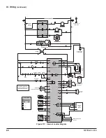
Страница 90: ...90 107774 02 4 18 Figure 11 8 Internal Wiring Connections Diagram XI Wiring continued...
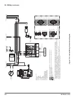
Страница 92: ...92 107774 02 4 18 Figure 11 9 TACO SR504 or Equivalent Zone Panel Wiring Connection Diagram XI Wiring continued...
Страница 93: ...93 107774 02 4 18 Figure 11 10 Sage Zone Control Circulator Panel Wiring Connection Diagram XI Wiring continued...
Страница 101: ...101 107774 02 4 18 Lighting and Operating Instructions XII Start Up and Checkout continued...
Страница 142: ...142 107774 02 4 18 XVI Repair Parts continued...
Страница 145: ...145 107774 02 4 18 XVI Repair Parts continued...
Страница 148: ...148 107774 02 4 18 XVI Repair Parts continued...
Страница 150: ...150 107774 02 4 18 XVI Repair Parts continued...
Страница 152: ...152 107774 02 4 18 XVI Repair Parts continued 120 121 122 123 124 125 126 127...
Страница 159: ...159 107774 02 4 18 SERVICE RECORD DATE SERVICE PERFORMED...
Страница 160: ...160 107774 02 4 18 U S Boiler Company Inc P O Box 3020 Lancaster PA 17604 1 888 432 8887 www usboiler net...


