


104
107774-02 - 4/18
5. Outdoor Air Reset
If an outdoor temperature sensor is connected
to the boiler and Outdoor Reset is enabled, the
Central Heat setpoint will automatically adjust
downwards as the outdoor temperature increases.
When the water temperature is properly matched
to heating needs there is minimal chance of room
air temperature overshoot. Excessive heat is not
sent to the room heating elements by “overheated”
(supply water temperature maintained too high
a setting) water. Reset control saves energy
by reducing room over heating, reducing boiler
temperature & increasing combustion efficiency
and, reducing standby losses as a boiler and
system piping cool down to ambient following
room over heating.
6. Boost Time
When the Central Heat Setpoint is decreased by
Outdoor Air Reset settings the Boost function can
be enabled to increase the setpoint in the event
that central heat demand is not satisfied for longer
than the Boost Time minutes. The Boost feature
increases the operating temperature setpoint by
10°F (5.6°C) every 20 minutes (field adjustable)
the central heat demand is not satisfied. This
process will continue until heat demand is
satisfied (indoor air is at desired temperature),
or the central heat setpoint is reached. Once the
heat demand is satisfied, the operating setpoint
reverts to the value determined by the Outdoor
Air Reset settings. If Boost Time is zero, then the
boost function is not used
.
7. Domestic Hot Water (DHW) Setpoint
Upon a DHW call for heat the setpoint is the user
entered DHW setpoint . When DHW has priority the
boiler will modulate in an attempt to maintain the
DHW set-point at the DHW sensor located near
the hot water connection. The factory default for
this setting is 120F.
8. Domestic Hot Water Priority (DHWP)
By default, when there is call for both CH and
DHW, the DHW demand takes priority for the
first 60 minutes of continuous simultaneous
demand. This means that all boiler output
will be directed to the DHW demand and the
boiler will modulate as needed to maintain
the temperature of the domestic hot water
leaving the boiler at the DHW set-point. Also
by default, during this time the system pump
will circulate water through the system even
though no heat is entering the system from the
boiler (this behavior increases the odds that a
“micro zone” demand can be satisfied using
the heat in a buffer tank or elsewhere in the
system).
At the end of the priority time, the boiler will
divert its entire output to the CH demand and
will revert to the CH set point as measured at
the supply sensor. At this point all heating of
DHW will end until there is an interruption in
either the CH or DHW demand. The default
60 minute DHW priority time can be increased
to as much as 120 minutes (see “Changing
Adjustable Parameters”).
C. Boiler Protection Features
1. Supply Water Temperature High Limit
The control is equipped with internal operating
control and high limit features. The control
monitors a dual element temperature sensor
that is mounted in the supply water manifold
and provides UL353 and UL1998 internal
safety algorithms. If supply water temperature
increases above the active setpoint plus diff
above, default 190°F (87.7°C) the boiler is cycled
off. If the temperature exceeds 210°F (98.9°C), a
manual reset hard lockout results. If the boiler is
responding to the internal Multiple Boiler Control
Sequencer, or an External EMS demand and the
supply water temperature increases above 190°F
(87.7°C) the control begins to reduce the blower
maximum speed setting and if the temperature
increases to 200°F (93°C) a forced recycle results.
Additionally, if the supply temperature rises faster
than the degrees Fahrenheit per second limit a
soft lockout is activated.
2. High Differential Temperature Limit
The Control monitors the temperature difference
between the return and supply sensors. If this
difference exceeds 52°F (29°C) the control
begins to reduce the maximum blower speed.
If temperature difference exceeds 62°F (34°C) a
forced boiler recycle results. The unit will restart
automatically once the temperature difference
has decreased and the minimum off time has
expired. If the temperature difference remains
above 72°F (40°C) for longer than 3 minutes a
manual reset hard lockout results.
3. Return Temperature Higher Than Supply
Temperature (Inversion Limit)
The Control monitors the supply and return
temperature sensors. If the return water
temperature exceeds the supply water temperature
for longer than a limit time delay the Control shuts
down the boiler and delays restart. If the inverted
temperature is detected more than five times, the
boiler manual reset Hard Lockout is set. This
condition is the result of incorrectly attaching the
supply and return piping.
XIII. Operation
(continued)
Содержание K2WTC-135
Страница 10: ...10 107774 02 4 18 Figure 4 1 Minimum Clearances To Combustible Construction IV Locating the Boiler continued...
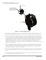
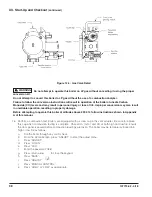
Страница 12: ...12 107774 02 4 18 Figure 5 1 Wall Layout Mounting Hole Location V Mounting The Boiler continued...
Страница 74: ...74 107774 02 4 18 Figure 9 2 Piping Method 1 Near Boiler Piping Heating Only IX System Piping continued...
Страница 76: ...76 107774 02 4 18 Figure 9 5 Piping Method 1 Near Boiler Piping Shaded Boiler Loop IX System Piping continued...
Страница 81: ...81 107774 02 4 18 X Domestic Hot Water Piping continued Figure 10 1 Domestic Hot Water Piping...
Страница 87: ...87 107774 02 4 18 Figure 11 6 J3 Field Wiring Figure 11 5 4 20 mA EMS Field Wiring XI Wiring continued...
Страница 89: ...89 107774 02 4 18 XI Wiring continued...
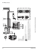
Страница 90: ...90 107774 02 4 18 Figure 11 8 Internal Wiring Connections Diagram XI Wiring continued...
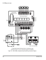
Страница 92: ...92 107774 02 4 18 Figure 11 9 TACO SR504 or Equivalent Zone Panel Wiring Connection Diagram XI Wiring continued...
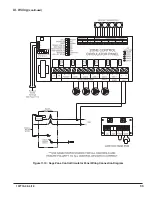
Страница 93: ...93 107774 02 4 18 Figure 11 10 Sage Zone Control Circulator Panel Wiring Connection Diagram XI Wiring continued...
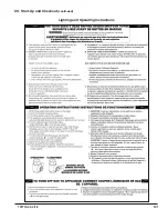
Страница 101: ...101 107774 02 4 18 Lighting and Operating Instructions XII Start Up and Checkout continued...
Страница 142: ...142 107774 02 4 18 XVI Repair Parts continued...
Страница 145: ...145 107774 02 4 18 XVI Repair Parts continued...
Страница 148: ...148 107774 02 4 18 XVI Repair Parts continued...
Страница 150: ...150 107774 02 4 18 XVI Repair Parts continued...
Страница 152: ...152 107774 02 4 18 XVI Repair Parts continued 120 121 122 123 124 125 126 127...
Страница 159: ...159 107774 02 4 18 SERVICE RECORD DATE SERVICE PERFORMED...
Страница 160: ...160 107774 02 4 18 U S Boiler Company Inc P O Box 3020 Lancaster PA 17604 1 888 432 8887 www usboiler net...


