


52
107774-02 - 4/18
VII. Venting
F. Assembly of DuraVent PolyPro Vent Systems (continued)
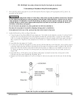
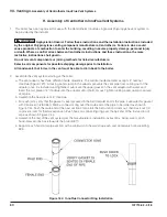
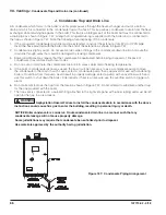
3. Installation of Air Intake System - Start assembly of the PVC air intake system at the boiler. Assembly of the air
intake system is done in the same manner as the vent system except as follows:
a. Drill a 7/32” clearance hole into the front side of the air intake adapter. Insert the first piece of PVC air
intake pipe into the air intake connection and drill a 1/8” tap hole into the PVC which lines up with the 7/32”
clearance hole and secure them together with a #10 x 1” sheet metal screw. Seal the joint between the intake
pipe and the adaptor with RTV.
b. All intake piping may be PVC.
c. There is a 0” minimum clearance between the air intake piping and all types of construction.
d. To the extent possible, pitch horizontal air intake piping towards the outside.
WARNING Asphyxiation Hazard. Vent systems made by M&G/DuraVent rely on gaskets for proper
sealing. When these vent systems are used, take the following precautions:
•
Make sure that gasket is in position and undamaged in the female end of the pipe.
•
Make sure that both the male and female pipes are free of damage prior to assembly.
•
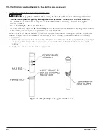
Only cut vent pipe as permitted by the vent manufacturer in accordance with their instructions. When
pipe is cut, the cut end must be square and carefully de-burred prior to assembly.
•
Use locking band clamps at all vent pipe joints.
•
Do not use anything other than soapy water to lubricate gaskets.
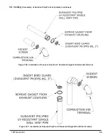
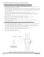
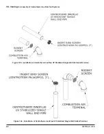
4. Installation of Horizontal Fitting Terminals (Terminal Option A):
a. See Figure 7.36 for proper orientation of twin pipe horizontal terminals. Outer edge of exhaust coupling must
be 10” or less from the wall surface. (Figure 7.9)
b. Remove the gasket from the end of the integral exhaust coupling and insert DuraVent Bird Guard #3PPS-BG
in it’s place.
c. Add PVC intake per instructions from Section VII - F.
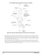
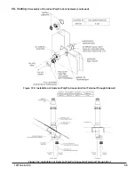
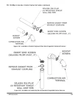
5. Installation of Vertical Fitting Terminals (Terminal Option H):
a. See Figure 7.37
for the proper orientation of twin pipe vertical terminals.
b. Remove the gasket from the end of the integral exhaust coupling and insert the installer supplied rodent
screen in it’s place.
c. A 180° bend (or two 90° elbows) are installed on the top of the air intake pipe. If two 90° elbows are used,
a rodent screen can be installed between them (Figure 7.37). If a 180° bend is used, a the rodent screen in
the open side of the bend, using a ring made of PVC pipe. If desired, the termination fittings can be attached
to the end of the intake pipes with field supplied stainless steel screws so that they can be later removed for
cleaning and inspection. If this is done, drill a clearance hole in these fittings and a tap hole in the end of the
intake pipes to accept these screws.
d. Use roof flashings and storm collars to prevent moisture from entering the building. Seal the roof flashing to
the roof using generally accepted practice for the type of roof on the installation. Apply RTV to seal the storm
collars to the vent and intake pipes.
NOTICE
The venting system must be free to expand and contract and supported in accordance with the
installation instructions included by the original Polypropylene venting component manufacturer, M&G/
DuraVent. Polypropylene pipe sections must be disengaged 1/4 to 5/8 in. (6 mm to 16 mm) per joint to
allow for thermal expansion.
Содержание K2WTC-135
Страница 10: ...10 107774 02 4 18 Figure 4 1 Minimum Clearances To Combustible Construction IV Locating the Boiler continued...
Страница 12: ...12 107774 02 4 18 Figure 5 1 Wall Layout Mounting Hole Location V Mounting The Boiler continued...
Страница 74: ...74 107774 02 4 18 Figure 9 2 Piping Method 1 Near Boiler Piping Heating Only IX System Piping continued...
Страница 76: ...76 107774 02 4 18 Figure 9 5 Piping Method 1 Near Boiler Piping Shaded Boiler Loop IX System Piping continued...
Страница 81: ...81 107774 02 4 18 X Domestic Hot Water Piping continued Figure 10 1 Domestic Hot Water Piping...
Страница 87: ...87 107774 02 4 18 Figure 11 6 J3 Field Wiring Figure 11 5 4 20 mA EMS Field Wiring XI Wiring continued...
Страница 89: ...89 107774 02 4 18 XI Wiring continued...
Страница 90: ...90 107774 02 4 18 Figure 11 8 Internal Wiring Connections Diagram XI Wiring continued...
Страница 92: ...92 107774 02 4 18 Figure 11 9 TACO SR504 or Equivalent Zone Panel Wiring Connection Diagram XI Wiring continued...
Страница 93: ...93 107774 02 4 18 Figure 11 10 Sage Zone Control Circulator Panel Wiring Connection Diagram XI Wiring continued...
Страница 101: ...101 107774 02 4 18 Lighting and Operating Instructions XII Start Up and Checkout continued...
Страница 142: ...142 107774 02 4 18 XVI Repair Parts continued...
Страница 145: ...145 107774 02 4 18 XVI Repair Parts continued...
Страница 148: ...148 107774 02 4 18 XVI Repair Parts continued...
Страница 150: ...150 107774 02 4 18 XVI Repair Parts continued...
Страница 152: ...152 107774 02 4 18 XVI Repair Parts continued 120 121 122 123 124 125 126 127...
Страница 159: ...159 107774 02 4 18 SERVICE RECORD DATE SERVICE PERFORMED...
Страница 160: ...160 107774 02 4 18 U S Boiler Company Inc P O Box 3020 Lancaster PA 17604 1 888 432 8887 www usboiler net...


