


47
107774-02- 4/18
VII. Venting
E. Assembly of CPVC/PVC Vent Systems (continued)
c. Fasten the vent base to the wall using the supplied screws and anchors. The anchors require the drilling of a
3/16” hole x 1-3/16” deep. Locate the holes using the vent base as a template.
d. Screw the vent cap to the vent base using the supplied screws.
e. Once the vent termination and pipes are secure seal the wall penetrations from the interior using a weather
resistant RTV sealant.
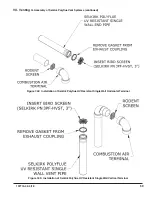
6. Installation of DiversiTech Low Profile Terminal (Terminal Option C) – See Figure 7.31:
a. Use vent plate as a guide to locate the openings for the vent and air intake pipes, as well as to locate the
holes for the mounting screws.
b. Drill two 3-1/8 holes through the wall for the vent and intake pipes.
c. Drill four 3/16 holes for the mounting screws.
d. Install the vent and intake pipe sections passing through the wall. Cut the pipes so that they protrude the
following distances from the surface on which the vent plate will be mounted:
• Vent: Between 1-3/4 and 2-1/4”
• Intake: Between ¼ and 1”
e. Seal pipe penetrations in wall with RTV (silicone sealant).
f. Mount the vent plate using the #8 x 2” screws and anchors provided with this kit.
g. Seal the vent plate to the wall with RTV.
h. Apply a bead of RTV around the OD of the vent pipe near its end.
i. Slide the vent cap over the vent pipe and secure to the wall plate with the #8 x 2” screws provided.
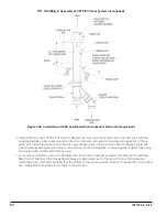
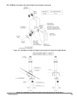
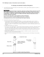
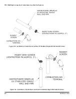
7. Installation of IPEX FGV or DiversiTech CVENT Concentric Vent Terminal (Terminal Options D,E,I & J) - This
terminal may be used for either horizontal or vertical venting. See Figure 7.33 for horizontal installation or Figure
7.34 for vertical installation. When PVC is used for venting, a 30” CPVC straight section and CPVC elbow must
be used prior to connection of the vent system to this terminal. If the vent system is too short to permit this, use
the IPEX FGV CPVC terminal:
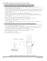
a. For horizontal installations at the planned location cut a round hole in the exterior wall 1/2” larger than the “C’
dimension indicated on Figure 7.32 for the size terminal being used. (See Section VII - B of this manual for
permitted terminal locations).
b. For vertical installations, cut a hole in the roof large enough to clear the concentric terminal at the location of
the terminal (see Section VII - C of this manual for permitted terminal locations).
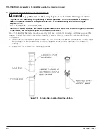
c. If desired, the terminal can be shortened. See Figure 7.32 for specific information on making the terminal kit
shorter based on the kit size being used. Cut the pipe squarely and de-burr both the OD and ID of the cut
edges.
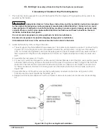
d. Cement the inner pipe section of PVC pipe supplied with this kit to the Wye fitting using a primer and cement
listed for use with PVC.
e. Cement the outer pipe to the Wye, being careful, to keep the inner and outer pipes concentric.
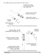
f. Slip the partially assembled terminal through the wall or ceiling from the inside and for horizontal installations
orient so that the side outlet on the Wye is on or above the horizontal plane.
g. For horizontal installations, seal the gap between the OD of the “outer pipe” and the exterior side of the wall
with RTV sealant.
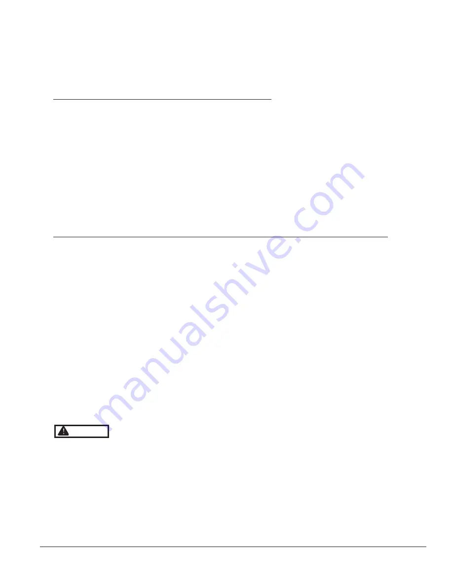
WARNING Asphyxiation Hazard. CPVC/PVC vent piping and fittings rely on glued joints for proper
sealing. Follow all manufacturer instructions and warnings when preparing pipe ends for joining and
using the primer and the cement.
When PVC is used with the concentric vent kit, a 30” CPVC straight section and elbow must be used prior
to connection of the vent system to this terminal. If the vent system is too short to permit this, use an FGV
CPVC terminal.
Do not operate boiler without the rain cap in place.
Method of securing and sealing terminals to the outside wall must not restrain the expansion of vent
pipe.
Содержание K2WTC-135
Страница 10: ...10 107774 02 4 18 Figure 4 1 Minimum Clearances To Combustible Construction IV Locating the Boiler continued...
Страница 12: ...12 107774 02 4 18 Figure 5 1 Wall Layout Mounting Hole Location V Mounting The Boiler continued...
Страница 74: ...74 107774 02 4 18 Figure 9 2 Piping Method 1 Near Boiler Piping Heating Only IX System Piping continued...
Страница 76: ...76 107774 02 4 18 Figure 9 5 Piping Method 1 Near Boiler Piping Shaded Boiler Loop IX System Piping continued...
Страница 81: ...81 107774 02 4 18 X Domestic Hot Water Piping continued Figure 10 1 Domestic Hot Water Piping...
Страница 87: ...87 107774 02 4 18 Figure 11 6 J3 Field Wiring Figure 11 5 4 20 mA EMS Field Wiring XI Wiring continued...
Страница 89: ...89 107774 02 4 18 XI Wiring continued...
Страница 90: ...90 107774 02 4 18 Figure 11 8 Internal Wiring Connections Diagram XI Wiring continued...
Страница 92: ...92 107774 02 4 18 Figure 11 9 TACO SR504 or Equivalent Zone Panel Wiring Connection Diagram XI Wiring continued...
Страница 93: ...93 107774 02 4 18 Figure 11 10 Sage Zone Control Circulator Panel Wiring Connection Diagram XI Wiring continued...
Страница 101: ...101 107774 02 4 18 Lighting and Operating Instructions XII Start Up and Checkout continued...
Страница 142: ...142 107774 02 4 18 XVI Repair Parts continued...
Страница 145: ...145 107774 02 4 18 XVI Repair Parts continued...
Страница 148: ...148 107774 02 4 18 XVI Repair Parts continued...
Страница 150: ...150 107774 02 4 18 XVI Repair Parts continued...
Страница 152: ...152 107774 02 4 18 XVI Repair Parts continued 120 121 122 123 124 125 126 127...
Страница 159: ...159 107774 02 4 18 SERVICE RECORD DATE SERVICE PERFORMED...
Страница 160: ...160 107774 02 4 18 U S Boiler Company Inc P O Box 3020 Lancaster PA 17604 1 888 432 8887 www usboiler net...


