


134
107774-02 - 4/18
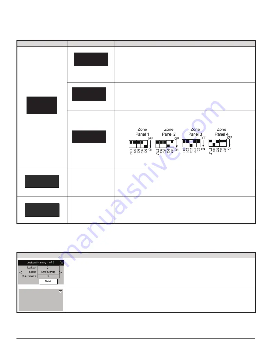
Indication
Condition
Possible Cause
Zone Panel
Setup
Flashing
Zone Panel 1
Setup
Flashing
Zone Panel 1 communication lost, typical for Panel 1 through 4: The zone panel’s
communication was established and then lost. Check the following to correct the
issue:
• Wiring between panel and boiler.
• Zone panel DIP switch settings have changed:
- Set Master/Slave switch to “Master”
- Set Zone Control switch ZC1 to “ON”
- Cycle power
Zone Panel Electronics Failure: A Zone Panel
Duplicate Zone: The Control has detected duplicate zone panel numbers. Check
the following to correct:
• Each Zone Control DIP Switch must be set to a Unique setting:
Note that when multiple ZC switches are set on ON the Zone Panel
is reported as Zone Panel 1.
Sequencer
Setup
Sequencer
Setup
Fault
This alarm is active if the slave boiler has lost communication with the Sequence
Master. Check the following:
- RJ 45 peer-to-peer network disconnected
- Sequencer Master was Enabled and then Disabled
- Master’s Boiler has been powered down.
- To clear fault restore communication or cycle power
Boiler Size
Setup
Boiler
Size
Fault
WARNING!
Boiler size setting may not match actual boiler size.
The Boiler size setting determines min, max and light-off blower speeds. Incorrect
boiler size can cause hazardous burner conditions and improper operation that may
result in PROPERTY LOSS, PHYSICAL INJURY, OR DEATH.
Refer to page 113 for boiler size setting instructions.
XV. Troubleshooting
(continued)
C. Help Screen Faults
Zone Panel
Failure
Flashing
Duplicate
Zone
Flashing
D. Help Screen Diagnostic Features
Indication
Possible Cause
Lockout History is stored in a first-in, first-out basis. Each History file is stored with boiler run hour of when the
lockout occurred.
The “When happened” and “Current” provide:
- “Current” is the run hour and status the boiler just finished.
- “When happened” is the run hour and status when the lockout occurred.
For Service Contact:
CONTRACTOR NAME
CONTRACTOR ADDRESS 1
CONTRACTOR ADDRESS 2
PHONE NUMBER
The user is given the contact information of the responsible service provider. Refer to page 116 for data entry
instructions.
Содержание K2WTC-135
Страница 10: ...10 107774 02 4 18 Figure 4 1 Minimum Clearances To Combustible Construction IV Locating the Boiler continued...
Страница 12: ...12 107774 02 4 18 Figure 5 1 Wall Layout Mounting Hole Location V Mounting The Boiler continued...
Страница 74: ...74 107774 02 4 18 Figure 9 2 Piping Method 1 Near Boiler Piping Heating Only IX System Piping continued...
Страница 76: ...76 107774 02 4 18 Figure 9 5 Piping Method 1 Near Boiler Piping Shaded Boiler Loop IX System Piping continued...
Страница 81: ...81 107774 02 4 18 X Domestic Hot Water Piping continued Figure 10 1 Domestic Hot Water Piping...
Страница 87: ...87 107774 02 4 18 Figure 11 6 J3 Field Wiring Figure 11 5 4 20 mA EMS Field Wiring XI Wiring continued...
Страница 89: ...89 107774 02 4 18 XI Wiring continued...
Страница 90: ...90 107774 02 4 18 Figure 11 8 Internal Wiring Connections Diagram XI Wiring continued...
Страница 92: ...92 107774 02 4 18 Figure 11 9 TACO SR504 or Equivalent Zone Panel Wiring Connection Diagram XI Wiring continued...
Страница 93: ...93 107774 02 4 18 Figure 11 10 Sage Zone Control Circulator Panel Wiring Connection Diagram XI Wiring continued...
Страница 101: ...101 107774 02 4 18 Lighting and Operating Instructions XII Start Up and Checkout continued...
Страница 142: ...142 107774 02 4 18 XVI Repair Parts continued...
Страница 145: ...145 107774 02 4 18 XVI Repair Parts continued...
Страница 148: ...148 107774 02 4 18 XVI Repair Parts continued...
Страница 150: ...150 107774 02 4 18 XVI Repair Parts continued...
Страница 152: ...152 107774 02 4 18 XVI Repair Parts continued 120 121 122 123 124 125 126 127...
Страница 159: ...159 107774 02 4 18 SERVICE RECORD DATE SERVICE PERFORMED...
Страница 160: ...160 107774 02 4 18 U S Boiler Company Inc P O Box 3020 Lancaster PA 17604 1 888 432 8887 www usboiler net...


