Note:
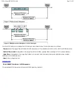
1. It is recommended to run one sequence with positive adjustments followed by another sequence with negative adjustments.
Performing the measurement at the maximum positive and negative frequency offset applicable to the line rate increases the
stress on the pointer processor.
2. The test procedure includes an initialization period followed by a cool down period of 30 seconds with no pointer movements.
10.4 SONET Functions > Trace Identifier
Tap the Trace Identifier icon to display the path trace testing screens shown below. There are dedicated tabs for Transmitted and
Received (expected) path traces and setups.
Transmitted Traces (Tx)
- J0 [Section]: Regenerator section trace
o Program a 1 or 16 byte identifier to check the connection between regenerators
TX150 e-Manual D07-00-023 Rev A02
Page 86 of 107

