background image


8. Acquiring CEPH Images (Optional) 

Green Smart User Manual                                                                  85    

EN

G

LISH


8.2 

Configuring Exposure Parameters 

To acquire CEPH images, 

6. Getting Started

 must be completed first. 


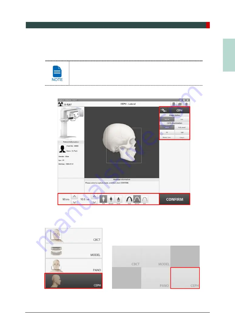
You can set the imaging parameters on Console Software running on 

the PC. (Touch Screen is Optional. In case the Touch Screen is 

included in the equipment, Touch Screen and Console Software are 

synchronized and display the same environmental settings.) 


1. 

Click the 

CEPH

 button on the Main Screen. 


    <Console Software>                         <Touch Screen> 

Содержание GREEN SMART

Страница 1: ...User Manual Version 1 23 English...

Страница 2: ......

Страница 3: ......

Страница 4: ......

Страница 5: ...effective use of this equipment Observe all cautions safety messages and warnings which appear in this manual Due to constant technological improvement the manual may not contain the most updated info...

Страница 6: ...ines 9 3 2 Electricity related Safety Precautions 13 3 3 Radiation Safety 15 3 4 Warnings 16 4 Imaging System Overview 19 4 1 System Components 19 4 2 Features 19 4 3 Standards and Regulations 20 4 4...

Страница 7: ...sure Parameters 106 9 3 Patient Positioning 111 9 4 X ray Exposure 116 9 5 Finishing the Scan 117 9 6 Checking the Captured Images 117 10 Acquiring 3D MODEL Scan Images 119 10 1 3D MODEL Scan Imaging...

Страница 8: ...5 1 Recommended X ray Exposure Tables 147 15 2 X ray Dose Data 157 15 3 Electromagnetic Compatibility EMC Information 166 15 4 Hand wrist Image Evaluation References 174 15 5 Acquiring Images for Pedi...

Страница 9: ...for Use Green Smart Model PHT 35LHS is intended to produce panoramic cephalometric or 3D digital x ray images It provides diagnostic details of the dento maxillofacial sinus and TMJ for adult and pedi...

Страница 10: ...medical radiation device and recognizing device connection installation operating conditions Language understanding Understanding how to use manuals English Korean Or Understanding other language pro...

Страница 11: ...authorized agent The equipment has been used normally by the User Manual The equipment damage or malfunction is not the result of an error on the part of the owner or the operator 2 2 Owner and Opera...

Страница 12: ...y with a warning may result in severe damage to the equipment or physical injury to the operator and patient CAUTION Indicates a situation that demands prompt and careful action a specific remedy or e...

Страница 13: ...urrent Label Type B Applied Equipment IEC 60601 1 Degree of protection against leakage current and electric shock Class 1 equipment Label Radiation hazard Label Indicates the authorized representative...

Страница 14: ...al waste and must be collected separately Label Warns ESD hazard MCU board Board package Indicates that this equipment is classified as a CLASS 1 LASER PRODUCT by IEC 60825 1 ED 2 regulations Label In...

Страница 15: ...l Information Green Smart User Manual 7 ENGLISH 2 4 1 Label Locations The label is attached to the right side of the equipment and it consists of 5 parts as below For Canada with CEPH For Canada witho...

Страница 16: ...inguished by Green Smart SC and Green Smart SP Green Smart SC CEPH included Green Smart SP CEPH not included CAUTION Label X ray Attention X ray on when equipment in operation X RAY GENERATOR Label 1...

Страница 17: ...ent and implement appropriate measures to remedy such irregularities General safety precautions Follow the instructions specified in this manual to ensure the safety of both the patient and the operat...

Страница 18: ...representative Any person or organization who installs an external door interlock switch is responsible for ensuring that it has a radiation indicator or equivalent alarm system to show the state of a...

Страница 19: ...umn operation time Max 2 min On 18 min Off Ratio 1 9 If the temperature inside the tube head reaches 60 C 140 F X ray exposure will cease and an error message will be displayed Normal X ray capabiliti...

Страница 20: ...quipment movement is not obstructed by the patient s clothing a medical device such as a wheelchair or the patient Do not leave the patient unattended around the equipment Remove all radio controlled...

Страница 21: ...er devices Do not connect this equipment to devices which are not designated as a part of the system Do not connect this equipment to a Multiple Portable Socket Outlet MPSO or extension cord which is...

Страница 22: ...tective measures Electrostatic discharge ESD ESD protective measures include Procedures for preventing electrostatic charge build up e g temperature control humidification conductive floor coverings a...

Страница 23: ...ing imaging the operator must maintain vocal visual contact with the patient from outside the shielded area The operator should continuously check the status of the patient and the equipment during im...

Страница 24: ...patient s radiological assessment conventional medical CT or MR should be used instead of dental cone beam imaging Green Smart system like other medical equipment uses high frequency electrical signa...

Страница 25: ...that is susceptible to explosion Do not place flammable materials near this equipment Do not operate the PC while the equipment is operating Failure to comply with this instruction may result in syst...

Страница 26: ...thorized technician complying with proper installation procedures For further details on installation refer to the Green Smart Model PHT 35LHS Installation Manual Security Capabilities It is recommend...

Страница 27: ...CEPH image acquisition 3D and 2D Auto Pano image acquisition by a single scan 3D scanning for Plaster Cast with FOV 10x8 5 cm Touch Screen implemented for easy use Optional DICOM Digital Imaging Comm...

Страница 28: ...ng in April 2007 for regulations compliance in accordance with the revised European Union s MDD Medical Devices Directive 93 42 EEC This equipment received the CSA certification mark in accordance wit...

Страница 29: ...4 Imaging System Overview Green Smart User Manual 21 ENGLISH 4 5 Imaging System Configuration PC Signal Input Output No Item 1 3D viewer License Key 2 Video output 3 Fiber optic cable Data in out...

Страница 30: ...t is different from the actual size 3 Ear Rods Secure the patient s head during CEPH imaging 4 Enclosed Component Storage The place where Bites Chinrest Ass y and the other components can be stored 5...

Страница 31: ...D Lamp Displays the status of X ray exposure Green Standby Yellow In operation 14 X ray Detector for PANO CBCT Xmaru1404CF Plus for PANO CBCT imaging sensor 15 Temple Supports Supports the patient s h...

Страница 32: ...r adjusting the height of the Chinrest 2 Horizontal Beam UP DOWN button Aligns the Horizontal Beam in PANO mode 3 Temple Supports OPEN CLOSE button Adjusts the Temple Supports for patient positioning...

Страница 33: ...e Supports OPEN CLOSE button Adjusts the Temple Supports for patient positioning 3 READY RETURN button Indicates that imaging is ready after parameter settings and the patient positioning are complete...

Страница 34: ...rlocked mutually therefore indicate the same environment setting values always CEPH button exists only when the CEPH imaging program is included in the equipment Do not allow the patient to control To...

Страница 35: ...option 2 CONFIRM button Confirms the settings and moves to the next step 3 BACK button Moves back to the modality PANO CEPH Optional CBCT MODEL selection screen 4 Settings button Adjusts Tube voltage...

Страница 36: ...he patient s head X ray intensity may be classified as Hard Normal or Soft Soft Normal Hard 4 Examination Program Selects between Normal and Special 5 Pano Option Selects between Normal Insight PAN an...

Страница 37: ...4 Imaging System Overview Green Smart User Manual 29 ENGLISH No Function Description 8 EXIT button Closes the Settings Screen and moves back to PANO Main Screen...

Страница 38: ...button Confirms the settings and moves to the next step 3 BACK button Moves back to the modality PANO CEPH Optional CBCT MODEL selection screen 4 Settings button Adjusts Tube voltage Tube current Gend...

Страница 39: ...ender Age group Selects patient s Gender Age group 3 X ray intensity Selects X ray intensity Depending on the circumference of the patient s head X ray intensity may be classified as Hard Normal or So...

Страница 40: ...tings and moves to the next step 3 BACK button Moves back to the modality PANO CEPH Optional CBCT MODEL selection screen 4 Settings button Adjusts Tube voltage Tube current Gender Age group X ray inte...

Страница 41: ...ient s Gender Age group 3 X ray intensity Selects X ray intensity Depending on the circumference of the patient s head X ray intensity may be classified as Hard Normal or Soft Soft Normal Hard 4 Image...

Страница 42: ...on programs 2 CONFIRM button Confirms the settings and moves to the next step 3 BACK button Moves back to the modality PANO CEPH Optional CBCT MODEL selection screen 4 Settings button Adjusts Tube vol...

Страница 43: ...een No Function Description 1 kVp mA control button Adjusts Tube voltage kVp and Tube current mA 2 Patient s gender age group Selects patient s gender age group 3 X ray intensity Selects X ray intensi...

Страница 44: ...il it pops up The Emergency Stop Switch is located at the bottom of the Vertical Frame 4 6 4 Exposure Switch The Exposure Switch allows the operator to control image acquisition from outside of the X...

Страница 45: ...J and Sinus modes For CBCT TMJ patients PC Polycarbonate Special Bite B For PANO edentulous patients PC Polycarbonate Normal Chinrest For Normal Bite ABS Acrylonitrile butadiene styrene copolymer Spec...

Страница 46: ...e image quality can be lower Do not place patients near the equipment and PC Item Specifications HP CPU E5 1607v4 4C 3 1GHz 2133 10MB Chipset Intel C612 RAM 2X8GB DDR4 2400 Registered RAM HDD 1TB SATA...

Страница 47: ...ing Patient Records and EzDent i EasyDent User Manual for more information Security Capabilities It is recommended to install and operate EzDent i EasyDent SW within a secure operating environment tha...

Страница 48: ...ed in the equipment Touch Screen and Console Software are synchronized and display the same environmental settings To improve program functions the Console Software may change without notice The Main...

Страница 49: ...rding to the patient s information gender age is displayed This tool adjusts the kVp and mA values and controls the power of the X ray to improve image quality If necessary adjust the kVp and mA value...

Страница 50: ...s for each mode PANO CEPH Optional CBCT and 3D MODEL Scan 11 Modality Selection button Returns to Modality Selection PANO CEPH Optional CBCT and MODEL screen 12 Rotation Test button Switches to the Ro...

Страница 51: ...our mouse After moving the bar release the mouse to play the current volume and save the current volume 15 Manual Reconstruction button Reconstructs the image manually when automatic image reconstruct...

Страница 52: ...5 Imaging Software Overview 44 Green Smart User Manual Left blank intentionally...

Страница 53: ...turning it on again Warm up the equipment for at least 5 minutes before the operation For the best image quality it is recommended to have a warm up phase for more than 30 minutes If the equipment ha...

Страница 54: ...system network equipped with Windows built in firewall Windows Defender antispyware tools and other commonly used 3rd party security tools and application systems The latest updates for anti virus so...

Страница 55: ...re outlined below EzDent i 1 Click the PATIENT tab and click the Add Patient icon from the main GUI window 2 Enter the required patient information Chart Number E Mail address First Name and Last Name...

Страница 56: ...eft corner of the EasyDent s main GUI window 2 Enter the required patient information Chart Number First Name and Last Name are required fields which must be filled in All other fields are optional bu...

Страница 57: ...the Name or Chart Number of the patient to be searched on the Patient Search panel and then click the Search button The information on the patient that fits the search condition appears Double click t...

Страница 58: ...t name of the patient and the virtual keyboard will pop up 2 Enter the Chart No First name or Last name of the patient by clicking the mouse on the virtual keyboard and click the Enter key The physica...

Страница 59: ...Dent i 1 Search and select the patient to be captured 2 Click ACQUISITION tab and select the imaging mode CT Panorama or Cephalo 3 The Main Screen for the selected mode appears From the Main Screen yo...

Страница 60: ...ist and click an imaging modality button to select on the upper left corner 2 The Main Screen for the selected mode appears From the Main Screen you can configure the imaging parameter settings prior...

Страница 61: ...gions at different angles Available PANO Options Mode Description Normal Provides a normal panoramic image Magic PAN Optional Provides a single optimal panoramic image having multiple focal images com...

Страница 62: ...low based on the ROI Region of Interest Examination Type Arch Selection ROI Sample Image PANO Examination Narrow Normal Wide Child Orthogonal Standard Right Front Left Orthogonal Bitewing Bitewing Inc...

Страница 63: ...art User Manual 55 ENGLISH Examination Type Arch Selection ROI Sample Image TMJ PA Open Optional TMJ PA Close Optional Sinus LAT Optional Sinus PA Bitewing imaging mode is activated only when Orthogon...

Страница 64: ...tients with a V shaped arch trajectory Typically for some females Normal Standard A panoramic imaging mode for adult patients with a normal arch trajectory Wide Standard A panoramic imaging mode for t...

Страница 65: ...f the teeth from the X ray exposure which is beamed perpendicularly between teeth Bitewing Bitewing Incisor mode is Optional A panoramic imaging mode to acquire an image only for the region of interes...

Страница 66: ...re a TMJ image in which the X ray beam is directed on the frontal TMJ with the patient s mouth open fully and close Sinus LAT Optional A special imaging mode to acquire a Sinus image in which X ray be...

Страница 67: ...be completed first If not you must return to the 6 Getting Started and finish the step first You can set the imaging parameters on Console Software running on the PC Touch Screen is Optional In case...

Страница 68: ...ns Console Software Touch Screen Mode Description Normal Provides a normal panoramic image Magic PAN Optional Provides a single optimal panoramic image having multiple focal images combined Minimizes...

Страница 69: ...ght PAN is selected among Pano Options Image Options are disabled 4 Make an Arch Selection Console Software Touch Screen Arch Selection Description Narrow Panoramic image of V shaped palatal arches sm...

Страница 70: ...ation options Bitewing Bitewing Incisor Optional Bitewing Right Bitewing Left select Orthogonal Arch in the Arch Selection panel When a Special Examination option is clicked PANO Examination panel is...

Страница 71: ...patient s head X ray intensity may be classified as Hard Normal or Soft Soft Normal Hard 8 The values of tube voltage and current are configured automatically according to the patient s gender age gro...

Страница 72: ...reen When you click CONFIRM button When you click CONFIRM button The Rotating Unit will move to its initial scanning position The Vertical Beam will be activated to make patient positioning easier The...

Страница 73: ...t laser beam correctly Otherwise the quality of images can be lower due to ghost images or expansion reduction of the images Getting prepared 1 Let the patient remove all the metal objects glasses ear...

Страница 74: ...a dry towel before the next patient 2 Use the Temple Supports OPEN CLOSE button on the control panel to widen the Temple Supports 3 Guide the patient to the inside of the equipment 4 Use the Column U...

Страница 75: ...in the posture as follows Close the mouth Place the tongue on the roof of the mouth Close the eyes Edentulous Patient Positioning 1 Remove the Normal Chinrest and insert the Special Chinrest into the...

Страница 76: ...that the patient s chin reaches the Chinrest 6 Guide the patient to stand in the center of the equipment and direct them to remain in the position outlined below Hold the handles tightly Press the ch...

Страница 77: ...sure to align the laser beam properly 1 Align the Vertical Beam with the center of the face Mid sagittal Line It s to prevent horizontal expansion of the image 2 Align the Horizontal Beam in a straigh...

Страница 78: ...the laser beam click the Temple Supports OPEN CLOSE button on the control panel to prevent the patient s head from moving Make sure that the Temple Supports are in CLOSE position before clicking the...

Страница 79: ...Special Chinrest Clean the Chinrest and the Bite with ethanol and wipe with a dry towel before the next patient 3 Use the Temple Supports Open Close button on the control panel to widen the Temple Sup...

Страница 80: ...the equipment it is difficult to maintain the proper position to get good images Be careful the patient does not touch the equipment with his her jaw 8 Let the patient maintain the posture as follows...

Страница 81: ...enlarged or reduced or ghost shadows may occur and lower the image quality Be sure to align the laser beam properly 1 Align the Vertical Beam with the center of the face Mid sagittal Line It s to pre...

Страница 82: ...the laser beam click the Temple Supports OPEN CLOSE button on the control panel to prevent the patient s head from moving Make sure that the Temple Supports are in CLOSE position before clicking the...

Страница 83: ...y Exposure Patient Positioning 1 Do you want to capture a TMJ Close image message will appear when the TMJ Open mode is completed Press Click OK button to begin TMJ Close mode Console Software Touch S...

Страница 84: ...it of the integrated Chinrest should touch the patient s acanthion point Let the patient maintain his her position until the operation is completed Laser Beam Aligning This is the same as the one for...

Страница 85: ...of the equipment so that the patient s chin reaches the Chinrest 6 Guide the patient to stand in the center of the equipment and direct them to remain in the position outlined below Hold the handles t...

Страница 86: ...posture as follows Close the mouth Place the tongue on the roof of the mouth Close the eyes As shown in the picture the support unit of the integrated Chinrest should touch the patient s acanthion po...

Страница 87: ...horizontal expansion of the image 2 Align the Horizontal Beam in a straight line to the Frankfurt Line on the patient s face Use the Horizontal Beam button on the control panel to position it Make su...

Страница 88: ...ng the image acquisition process Do not operate the PC during exposure Doing so may cause the system to malfunction Let the patient close the eyes during the operation To acquire optimized images inst...

Страница 89: ...ple Supports and guide the patient out of the equipment 2 For Normal Bite remove the Sanitary Vinyl Cover from the Bite 3 Press READY button to bring the Rotating Unit back to its initial position 7 6...

Страница 90: ...7 Acquiring PANO Images 82 Green Smart User Manual Left blank intentionally...

Страница 91: ...area the sinus and the hard palate Measures the angles formed by the connecting lines between the cranial measurement points to further assess the growth of the facial region It s widely used in Ortho...

Страница 92: ...the side wall of the maxillary sinus and zygomatic arch fractures Also used to study the inner and outer alar plates and holes at the base of the skull SMV Waters view Used to study the frontal sinus...

Страница 93: ...must be completed first You can set the imaging parameters on Console Software running on the PC Touch Screen is Optional In case the Touch Screen is included in the equipment Touch Screen and Consol...

Страница 94: ...ion On Touch Screen click Settings button before selecting options Console Software Touch Screen 3 Select an examination program in the CEPH Examination panel Console Software Touch Screen 4 The Gende...

Страница 95: ...the patient s head X ray intensity may be classified as Hard Normal or Soft Soft Normal Hard 6 The values of tube voltage and current are configured automatically according to the patient s gender ag...

Страница 96: ...CONFIRM button when exposure parameter setting is completed Console Software Touch Screen When you click CONFIRM button The DAP Dose Area Product Scan Time and Exposure Time will be displayed below t...

Страница 97: ...per direction Correct posture reduces the shadow cast by the patient s cervical spine and allows clear image acquisition Metal implants or bridges may reduce the quality of the images Getting prepared...

Страница 98: ...w 2 Leave enough space between the Ear Rods Use the Porion Position Reference Indicator that appears in the acquired image to easily confirm the location of Porion 3 Guide the patient to the CEPH unit...

Страница 99: ...ositioner with the patient s nation by adjusting its height 7 Align horizontally so the patient s Frankfurt Line is parallel to the floor 8 Direct the patient to swallow first before closing the mouth...

Страница 100: ...ner to the PA Waters view Carpus mode Positioning Marker as shown below 2 Fold the Nasal Positioner up The Nasal Positioner is not used in PA mode 3 Guide the patient to the CEPH unit 4 Ask the patien...

Страница 101: ...s to the patient 6 During the operation properly align the Ear Rods to the patient s ears so his her head does not move 7 Align horizontally so the patient s Frankfurt Line is parallel to the floor 8...

Страница 102: ...e Patient Positioning 1 Turn the Nasal Positioner to the SMV mode Positioning Marker as shown below 2 Fold the Nasal Positioner up The Nasal Positioner is not used in SMV mode 3 Guide the patient to t...

Страница 103: ...ent 6 During the operation properly align the Ear Rods to the patient s ears so his her head does not move 7 Carefully tilt the patient s head back and adjust so his her Frankfurt Line is vertical wit...

Страница 104: ...e patient s shoulders are level and that his her neck is relaxed 5 Use the Column UP DOWN button or switch option to adjust the height of the CEPH unit to approximately match the height of the patient...

Страница 105: ...8 Acquiring CEPH Images Optional Green Smart User Manual 97 ENGLISH 8 Click the READY button The x ray exposure has not started yet 9 Now go to 8 4 X ray Exposure to start the exposure...

Страница 106: ...e patient Installing the Carpus Plate 1 Turn the Nasal Positioner to the PA Waters view Carpus mode Positioning Marker as shown below 2 Fold the Nasal Positioner up The Nasal Positioner is not used in...

Страница 107: ...ht hand splayed on the Carpus Plate as shown below Make sure that the patient does not bend his her fingers 2 Ask the patient to close his her eyes and stand still until the image acquisition is compl...

Страница 108: ...ng the operation To acquire optimized images instruct the patient to hold his her breath and not to swallow Also don t let the patient move until the Temple Supports are open 1 Get out of the X ray ro...

Страница 109: ...images can be reconstructed and converted to DICOM format The exported images can be confirmed in EzDent i EasyDent Refer to the EzDent i EasyDent User Manual for more information 1 The images are tr...

Страница 110: ...8 Acquiring CEPH Images Optional 102 Green Smart User Manual Left blank intentionally...

Страница 111: ...em to 3D sliced images Examination Programs It is classified as below based on the FOV Available FOVs cm ROI Description 10x8 5 Occlusion Center Covers both maxillary and mandibular structures includi...

Страница 112: ...Right Molar Maxilla Left Molar Maxilla Incisor Maxilla Right Maxilla Left Mandible Right Molar Mandible Left Molar Mandible Incisor Mandible Right Mandible Left Covers 3 4 areas through capturing ROIs...

Страница 113: ...s Green Smart User Manual 105 ENGLISH Special Option Auto Pano 2D images of conventional panoramic view are available with the specific FOVs For more details on Auto Pano please refer to 9 2 Configuri...

Страница 114: ...completed first You can set the imaging parameters on Console Software running on the PC Touch Screen is Optional In case the Touch Screen is included in the equipment Touch Screen and Console Softwa...

Страница 115: ...ical option and Horizontal option are set as below by default For FOV 5x5 Vertical option and Tooth option are available Available FOV cm Vertical option Horizontal option Tooth option 10x8 5 Occlusio...

Страница 116: ...een click Settings button before selecting options Console Software Touch Screen 4 Select a Voxel Size MAR Metal Artifact Reduction function is applied automatically if there are metal objects in the...

Страница 117: ...d X ray intensity may be classified as Hard Normal or Soft Soft Normal Hard 7 The values of tube voltage and current are configured automatically according to the patient s gender age group and X ray...

Страница 118: ...oftware Touch Screen When you click CONFIRM button The Rotating Unit will move to its initial scanning position The Vertical Beam will be activated to make patient positioning easier The DAP Dose Area...

Страница 119: ...t laser beam correctly Otherwise the quality of images can be lower due to ghost images or expansion reduction of the images Getting prepared 1 Let the patient remove all the metal objects glasses ear...

Страница 120: ...OPEN CLOSE button on the control panel to widen the Temple Supports 3 Guide the patient to the equipment 4 Use the Column UP DOWN button or switch option to adjust the height of the equipment so that...

Страница 121: ...9 Acquiring CBCT Images Green Smart User Manual 113 ENGLISH 7 Let the patient maintain the posture as follows Close the mouth Place the tongue on the roof of the mouth Close the eyes...

Страница 122: ...e Up Down button or switch option to adjust the height of the equipment so that the patient s chin reaches the Chinrest 6 Guide the patient to stand in the center of the equipment and direct them to r...

Страница 123: ...lustration for reference only Actual FOV may vary from the image as shown above 1 Align the Vertical Beam with the center of the face Mid sagittal Line It s to prevent horizontal expansion of the imag...

Страница 124: ...ing the image acquisition process Do not operate the PC during exposure Doing so may cause the system to malfunction Let the patient close the eyes during the operation To acquire optimized images ins...

Страница 125: ...atient out of the equipment 2 For Normal Bite remove the Sanitary Vinyl Cover from the Bite 3 Press READY button to bring the Rotating Unit back to its initial position 9 6 Checking the Captured Image...

Страница 126: ...9 Acquiring CBCT Images 118 Green Smart User Manual Left blank intentionally...

Страница 127: ...es with the X ray beam scanning the Plaster Cast and reconstructs them to 3D sliced images and converts the sliced images into 3D modeling surface data Examination Programs It is classified as below b...

Страница 128: ...ted must be completed first You can set the imaging parameters on Console Software running on the PC Touch Screen is Optional In case the Touch Screen is included in the equipment Touch Screen and Con...

Страница 129: ...selected automatically based on the patient information If necessary you can select the option manually Console Software Touch Screen 4 Select X ray intensity Console Software Touch Screen 5 The valu...

Страница 130: ...e Software Touch Screen When you click CONFIRM button The Rotating Unit will move to its initial scanning position The Vertical Beam will be activated to make patient positioning easier The DAP Dose A...

Страница 131: ...an Jig Laser Beam Aligning 1 Put the Plaster Cast on the MODEL Scan Jig Whether the Plaster Cast is for Maxilla or Mandibular place it flat side down 2 Align the Mid sagittal plane Laser Beam to the c...

Страница 132: ...The image appears on the screen During X ray exposure the status appears as follows The LED light of the Exposure Switch turns yellow The LED light on the top of the equipment turns yellow An alert so...

Страница 133: ...Refer to the EzDent i User Manual for more information 1 The images are transferred to EzDent i automatically 2 The images are automatically saved if automatic save option is configured as default If...

Страница 134: ...10 Acquiring 3D MODEL Scan Images 126 Green Smart User Manual Left blank intentionally...

Страница 135: ...y again Failure of the Control PC s connection Check the connection status of Communication Port Optic which connects the PC to the equipment If the Exposure Switch is not functioning Cause Actions to...

Страница 136: ...e monk tank When the temperature of the monk tank is greater than or equal to 55 C do not emit X rays and cool down the mono tank before use H009 Error occurs when the inverter current has a problem d...

Страница 137: ...X rays again check whether the same error occurs Check the input power DC 300 V of the inverter board After replacing the inverter board check for error after X ray emission If the same error occurs r...

Страница 138: ...or or sensor H036 Error occurs during movement from the 1 axis collimator s left right origin position Check the connection lines for the motor and origin sensor If any problem replace the motor or se...

Страница 139: ...uipment Do not use any cleaning products which contain silicon They could potentially damage the equipment s electrical components The following table summarizes the standard cleaning procedures to be...

Страница 140: ...the input fuses which must comply with the manufacturer s specifications As a precaution against fire the replacement should be one in the same type and range There are no user serviceable parts insid...

Страница 141: ...power cord are not heated abnormally Daily Confirm that the LED indicator turns yellow when the Exposure Switch is pressed Ensure that the LED indicator remains yellow for the entire duration of the...

Страница 142: ...12 Cleaning and Maintenance 134 Green Smart User Manual Left blank intentionally...

Страница 143: ...of in accordance with disposal regulations IEC 60601 1 6 8 2 j Parts Materials Recyclable To the special disposal site Hazardous waste Needs Separate Collection Frame and Covers Aluminum and plastics...

Страница 144: ...13 Disposing of the Equipment 136 Green Smart User Manual Left blank intentionally...

Страница 145: ...14 Technical Specifications Green Smart User Manual 137 ENGLISH 14 Technical Specifications 14 1 Mechanical Specifications 14 1 1 Dimensions unit mm...

Страница 146: ...m L x 1113 mm W x 2336 mm H with Base With CEPH unit 1390 3 mm L x 1882 3 mm W x 2304 5 mm H without Base 1390 3 mm L x 1882 3 mm W x 2336 mm H with Base Rotating Unit Vertical Movement Max 800 mm Ins...

Страница 147: ...mA increment for PANO and CEPH Cooling Cooling Protect Optional fan cooling 60 Total filtration Min 2 5 mm Al Default filtration 1 0 mm Al Added filtration 1 5 mm Al Fixed PANO and CEPH mode 1 5 mm Al...

Страница 148: ...4 14 11 3 60 90 4 14 11 1 60 90 4 14 9 2 60 90 4 14 7 7 60 90 4 14 7 0 60 90 4 14 6 8 60 90 4 14 6 7 60 90 4 14 6 1 60 90 4 14 5 8 60 90 4 14 5 7 60 90 4 14 5 2 60 90 4 14 5 0 60 90 4 14 3 7 60 90 4 1...

Страница 149: ...14 Technical Specifications Green Smart User Manual 141 ENGLISH Maximum Rating Charts Emission Filament Characteristics...

Страница 150: ...14 Technical Specifications 142 Green Smart User Manual Anode Thermal Characteristics X ray Housing Assembly Tube Characteristics...

Страница 151: ...135 8 mm PANO 5 9 mm X 135 8 mm 15 6 mm x 259 mm Frame Rate 308 Hz 4X4 binning 330 Hz 2x2 binning Analogue Digital Conversion 14 bits Operating condition 10 35 Temperature 10 75 Humidity Storage condi...

Страница 152: ...oltage kVp 10 Tube Current mA 20 Exposure Time s 5 50 ms The input line voltage depends on the local electrical distribution system Allowable input voltage fluctuation requirement 10 Mode of operation...

Страница 153: ...ion of the tube voltage tube current exposure time Tube Voltage kVp 10 Tube Current mA 20 Exposure Time s 5 50 ms according to IEC 60601 2 63 The mains resistance should not exceed 0 045 ohms at 100 V...

Страница 154: ...14 Technical Specifications 146 Green Smart User Manual Left blank intentionally...

Страница 155: ...ge Option Gender Age group X ray Intensity Tube Voltage kVp Tube Current mA PANO Examination High Resolution Man Hard 75 12 Normal 74 12 Soft 73 12 Woman Hard 74 12 Normal 73 12 Soft 72 12 Child Hard...

Страница 156: ...rmal 73 14 Soft 72 14 Child Hard 68 12 Normal 67 12 Soft 66 12 PANO Option Insight PAN Mode Image Option Gender Age group X ray Intensity Tube Voltage kVp Tube Current mA PANO Examination SPECIAL Exam...

Страница 157: ...nation Narrow Standard 14 1 13 5 7 0 7 0 Right 14 1 6 8 7 0 3 5 Front 14 1 11 3 7 0 5 8 Left 14 1 6 8 7 0 3 5 Normal Standard 14 1 13 5 7 0 7 0 Right 14 1 6 8 7 0 3 5 Front 14 1 11 3 7 0 5 8 Left 14 1...

Страница 158: ...7 0 2 8 SPECIAL Examination TMJ LAT Open 14 1 6 7 14 1 6 7 TMJ LAT Close TMJ PA Open Optional 10 0 6 1 10 0 6 1 TMJ PA Close Optional Sinus LAT Optional 4 0 3 7 4 0 3 7 Sinus PA 8 8 7 7 8 8 7 7 For I...

Страница 159: ...0 Soft 88 15 0 Woman Hard 90 15 0 Normal 88 15 0 Soft 86 15 0 Child Hard 88 15 0 Normal 86 15 0 Soft 84 15 0 Green Man Hard 92 16 0 Normal 90 16 0 Soft 88 16 0 Woman Hard 90 16 0 Normal 88 16 0 Soft...

Страница 160: ...oft 88 14 0 Woman Hard 90 14 0 Normal 88 14 0 Soft 86 14 0 Child Hard 88 14 0 Normal 86 14 0 Soft 84 14 0 Green Man Hard 92 15 0 Normal 90 15 0 Soft 88 15 0 Woman Hard 90 15 0 Normal 88 15 0 Soft 86 1...

Страница 161: ...ime s Lateral 3 9 3 9 1 9 1 9 Full Lateral Optional 5 4 5 4 3 9 3 9 PA 4 9 4 9 2 4 2 4 SMV 4 9 4 9 2 4 2 4 Waters view 4 9 4 9 2 4 2 4 Carpus 4 9 4 9 2 4 2 4 Scan Time The actual time that the equipme...

Страница 162: ...ull arch area 10x8 5 cm Adult mode FOV 10x7 cm Child mode Exposure Condition Scan Time 18 0 s FOV cm Image Option Gender Age Group X ray Intensity Tube Voltage kVp Tube Current mA 10x8 5 10x7 5x5 High...

Страница 163: ...0x8 5 with Auto Pano 0 2 120 267 0 3 125 84 10x7 0 2 90 202 0 3 93 60 5x5 0 08 162 466 0 12 128 139 The above data is obtained from a computer system which is based on Intel i7 6700 and NVIDIA Geforce...

Страница 164: ...Exposure Time s 10x8 5 18 0 16 4 Scan Time The actual time that the equipment shoots the plaster cast except for the initial acceleration and late deceleration stages Exposure Time The actual time th...

Страница 165: ...G 07E22T2 Tube D 052SB DAP Dose Area Product is a quantity used in assessing the radiation risk from diagnostic X ray examination procedures It is defined as the absorbed dose multiplied by the area i...

Страница 166: ...2 0 mA 13 5 s 110 PANO Child Normal High Resolution 67 kVp 10 0 mA 11 5 s 55 PANO Adult Man Normal Green 74 kVp 14 0 mA 7 0 s 65 PANO Child Normal Green 67 kVp 12 0 mA 6 7 s 35 PANO Adult Man Insight...

Страница 167: ...A 16 4 s 530 CT FOV 10x7 Adult Man Green 79 kVp 5 0 mA 16 4 s 210 CBCT FOV 5x5 Maxilla Adult Man High Resolution 94 kVp 8 7 mA 11 0 s 290 CBCT FOV 5x5 Maxilla Adult Man Green 79 kVp 5 0 mA 11 0 s 115...

Страница 168: ...hat is not purposed and this document evaluates leakage dose amount based on following standard defined by IEC regulation and has been performed by covering each collimator region in use Standard Nati...

Страница 169: ...9 0 079 8 0 070 22 7 0 061 7 0 061 45 3 0 026 4 0 035 75 2 0 018 3 0 026 90 1 0 009 1 0 009 100 3 0 026 2 0 018 110 3 0 026 3 0 026 120 4 0 035 4 0 035 130 4 0 035 4 0 035 140 5 0 044 5 0 044 150 3 0...

Страница 170: ...10 0 088 22 7 0 061 7 0 061 45 4 0 035 4 0 035 75 7 0 061 7 0 061 90 1 0 009 1 0 009 100 4 0 035 4 0 035 110 4 0 035 4 0 035 120 4 0 035 4 0 035 130 5 0 044 5 0 044 140 2 0 018 2 0 018 150 1 0 009 2...

Страница 171: ...ak kVp 90 Applied Tube Current mA 14 Results Direction mR hr mGy hr 0 9 0 079 22 7 0 061 45 3 0 026 75 2 0 018 90 1 0 009 100 3 0 026 110 3 0 026 120 4 0 035 130 4 0 035 140 5 0 044 150 3 0 026 160 2...

Страница 172: ...237 22 13 0 114 12 0 105 45 8 0 070 8 0 070 75 12 0 105 12 0 105 90 3 0 026 7 0 061 100 6 0 053 6 0 053 110 6 0 053 7 0 061 120 7 0 061 6 0 053 130 5 0 044 5 0 044 140 2 0 018 1 0 009 150 1 0 009 2 0...

Страница 173: ...ignificant zones of occupancy and the effectiveness of protective shielding facility around the patient s position This information states the identity and intended position of the tested phantom and...

Страница 174: ...ested Model PANO Normal High Resolution Distance from focal point m 1 2 Applied Tube Voltage Peak kVp 90 Applied Tube Current mA 14 Results Direction Normal 13 5 s mR hr 1 m 3 3 ft 1 5 m 4 9 ft 2 m 6...

Страница 175: ...ted Model PANO Insight PAN Distance from focal point m 1 2 Applied Tube Voltage Peak kVp 90 Applied Tube Current mA 14 Results Direction Insight PAN 13 5 s mR hr 1 m 3 3 ft 1 5 m 4 9 ft 2 m 6 6 ft 0 4...

Страница 176: ...0x8 5 High Resolution Distance from focal point m 1 2 Applied Tube Voltage Peak kVp 99 Applied Tube Current mA 12 Results Direction FOV 10x8 5 16 4 s mR hr 1 m 3 3 ft 1 5 m 4 9 ft 2 m 6 6 ft 0 361 85...

Страница 177: ...uitable for use in all establishments other than domestic and may be used in domestic establishments and those directly connected to the public low voltage power supply network that supplies buildings...

Страница 178: ...to line s 2 kV line s to earth 1 kV line s to line s 2 kV line s to earth Main power quality should be that of a typical commercial or hospital environment Voltage dips short interruptions and voltage...

Страница 179: ...ncluding cables than the recommended separation distance calculated from the equation applicable to the frequency of the transmitter Recommended separation distance Where P is the maximum output power...

Страница 180: ...ctromagnetic environment in which radiated RF disturbances are controlled The customer or the user of the PHT 35LHS can help Prevent electromagnetic interference by maintaining a minimum distance betw...

Страница 181: ...ss the electromagnetic environment due to fixed RF transmitters an electromagnetic site survey should be considered If the measured field strength in the location in which the PHT 35LHS is used exceed...

Страница 182: ...tem of Skeletal Maturation Assessment SMA The System uses only four stages of bone maturation all found at six anatomical sites located on the thumb third finger fifth finger and radius as seen Fig 1...

Страница 183: ...sites in the hand wrist Fig2 Radiographic identification of skeletal maturity indicators A The width of epiphysis as wide as diaphysis 1 Third finger Proximal phalanx 2 Third finger middle phalanx 3 F...

Страница 184: ...scent development are found on these six sites Fig 1 orange circles Fig3 Eleven Skeletal maturity indicators SMIs A systematic observational scheme such as that shown in the figure above can further f...

Страница 185: ...15 Appendices Green Smart User Manual 177 ENGLISH...

Страница 186: ...position throughout the exposure 2 Move the Chinrest into a position that is slightly higher than the patient s chin height before requesting that the patient place chin on the rest Direct the patien...

Страница 187: ...pediatric patient while minimizing the occurrence of retakes that result from the radiographic error Producing A Quality Panoramic Image A quality panoramic radiograph should image all of the teeth e...

Страница 188: ...ral alignment and chin rest to correctly locate the superior inferior dimension or how far up or down the chin should be positioned 4 10 Panoramic x ray machines are available with a mirror and laser...

Страница 189: ...eeth Figure 3 When the arches are positioned too far posteriorly the anterior teeth will appear broad or widened If the position is excessively posterior anterior teeth may be completely blurred from...

Страница 190: ...rom incorrect lateral positioning the midsagittal plane must be positioned perpendicular to the floor Most panoramic x ray machines have a head positioner and or laser light beam guide along with a mi...

Страница 191: ...at downward turned appearance to the occlusal plane Figure 5 The condyles flare out and off the edges of the image and the palate appears as a widened thick dense radiopacity This positioning error re...

Страница 192: ...chine allowing the operator to place the chin rest in a position that is slightly higher than the patient s chin The patient is then requested to move into the overhead assembly of the machine and rem...

Страница 193: ...igher diagnostic yields References 1 Public Health Service Food and Drug Administration American Dental Association Council on Dental Benefits Program Council on Dental Practice Council on Scientific...

Страница 194: ...ry exposure to X radiation and to identify individuals who may benefit from a radiographic examination Every prescription of radiographs should be based on an evaluation of the individual patient bene...

Страница 195: ...rotocols The doses to the thyroid salivary glands and brain ranged from 0 068mSv to 1 131mSv 0 708mSv to 2 009mSv and 0 031mSv to 1 584mSv respectively The skin and red bone marrow have received much...

Страница 196: ...lens and thyroid were 32 7 mGy for a lens in brain CT and 17 2 mGy for thyroid in neck CT Seventy Fifth percentile of effective dose distribution in brain CT was approximately the same as the diagnos...

Страница 197: ...tibility ENT Ear Nose and Throat ESD Electrostatic Discharge EUT Equipment Under Test FDD Focal spot to Detector Distance FOD Focal spot to Object Distance FOV Field of View FPD Flat Panel Detector IE...

Страница 198: ...15 Appendices 190 Green Smart User Manual STL Stereo Lithography TMJ Temporomandibular Joint UHD Ultra High Definition...

Страница 199: ...formation contact your VATECH representative Tel 82 1588 9510 Email gcs vatech co kr Website www vatech co kr Headquarters 13 Samsung 1 ro 2 gil Hwaseong si Gyeonggi do 18449 Korea Factory 13 Samsung...

Страница 200: ......

Отзывы: