Installation 5
0020261188_00 ecoTEC plus Installation and maintenance instructions
17
2.
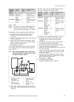
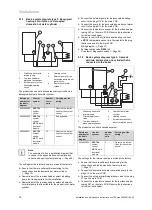
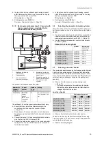
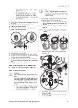
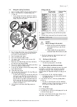
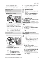
Install the air/flue pipe using the set-up instructions.
5.6.2
B23 installation
A flue system for permitted unit type B23 (open-flued gas-
fired wall-hung boilers) requires careful planning and imple-
mentation.
▶
Observe the product's technical data when planning.
▶
Use the recognised rules of technology.
5.6.3
Information and specifications for installing
the B23P
Applicability:
B23P
The flue system must at least correspond to the classification
T 120 P1 W 1 in accordance with EN 1443. The maximum
pipe length must be calculated based on the permissible
pressure difference in the technical data.
The maximum pipe length (straight pipe only) corresponds
to the maximum permitted flue pipe length without any el-
bows. If elbows are used, the maximum pipe length must be
reduced in accordance with the dynamic flow characteristics
of the elbows. Elbows must not be connected directly after
one another as this method dramatically increases pressure
losses.
In particular, if the flue pipe is installed in cold rooms or out-
side of the building, the freezing point on the surface of the
inside of the pipe may be reached. Since the product is de-
signed in accordance with EN 13384-1, this problem should
not occur with the minimum boiler load at a flue gas temper-
ature of 40 °C. The product must not be connected to a cas-
cade flue system that is being used by other products.
▶
Observe the applicable international, national and local
regulations for flue systems, in particular for installations
in living rooms. Inform the end user how to correctly op-
erate the product.
5.6.4
Installation with flue non-return flap
When installing a flue non-return flap, you must set the min-
imum output in order to prevent ignition problems.
▶
Use diagnostics code
D.085
to set the minimum output.
(
→
Page 26)
Setting the minimum output of the product
D.085
(factory
setting)
Setting D.085 for
the flue non-
return flap
VC 406/5-5 (E-DE)
8 kW
10 kW
VC 406/5-5 (LL-DE)
8 kW
10 kW
VC 476/5-5 (E-DE)
8 kW
10 kW
VC 476/5-5 (LL-DE)
8 kW
10 kW
VC 636/5-5 (E-DE)
11 kW
13 kW
VC 636/5-5 (LL-DE)
11 kW
13 kW
5.6.5
Air/flue pipe in long lengths
Applicability:
Germany
OR Luxemburg
▶
If the length of the air/flue pipe is between 15 and 18
metres, adjust the setting for the product code
D.093
in
accordance with the following table.
Changing the product code
VC 406/5-5 (E-DE)
171
VC 406/5-5 (LL-DE)
171
VC 476/5-5 (E-DE)
174
VC 476/5-5 (LL-DE)
174
5.7
Electrical installation
Danger!
Risk of death from electric shock!
Power supply terminals
L
and
N
remain live
even if the on/off button is turned off:
▶
Switch off the power supply.
▶
Secure the power supply against being
switched back on again.
Only qualified electricians may carry out the electrical install-
ation.
5.7.1
Opening/closing the electronics box
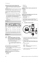
5.7.1.1 Opening the electronics box
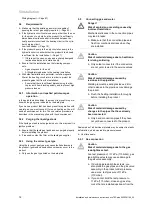
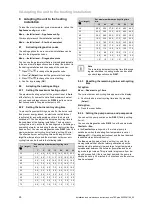
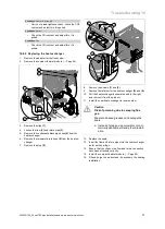
1.
Remove the front casing. (
→
Page 9)
A
C
B x 2
x 2
2.
Tilt the electronics box forward.
3.
Loosen the four clips from the retainers
(A)
and
(B)
on
the electronics box.
4.
Hinge the cover
(C)
up.

